310
Se
tt
ing I
n
s
p
e
c
tio
n C
on
d
it
ions
C
h
ap
te
r 4
4.19 Marker
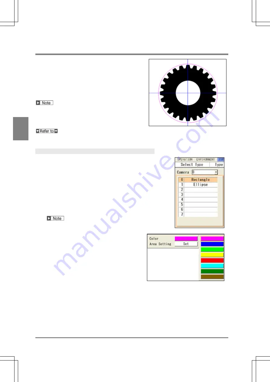
Marker is the function that displays figures of line, rectangle,
circle, polygon or cross line on the screen window of RUN
menu. This function can display an image on the screen like
indicating a guide to position the object with no effect on the
inspection time. This function also can move the created
marker by inputting commands from the external device.
Up to eight markers can be set for each product type per
camera.
Creating and editing markers are operated in SETUP Menu.
However, they can be displayed only in the RUN Menu.
Markers cannot be displayed on the screen window in
SETUP menu.
Marker display: see page 324.
Creating Marker
1.
In SETUP menu, select "TYPE" > "Marker Display"
from the menu bar.
The marker menu is displayed.
The marker list shows marker numbers and their
shapes.
2.
Specify a camera No. to set a marker.
3.
Select the marker list and then select a marker
number from 0 - 7 to create.
The marker shape of larger number is displayed in front
on the screen window.
For example, if you create markers in the same size
and on the same position, setting No.0 in blue and No.7
in yellow, only the yellow marker No.7 is displayed on
the screen.
4.
Select a color from the eight colors.
5.
Select “Set” of "Area Setting" to set area shape and
area.
The procedure to select area shape and to specify area
is the same as of checker area.
It can be set for the captured image and a total of 9
screens surrounding it. However, in the case of the
marker of cross line, it can be set and displayed only in
the area of the captured image.
6.
After setting is completed, press the CANCEL key.
When you close the marker setting window, the marker
on the screen disappears which was displayed while
you are setting it. This is because SETUP menu cannot
display markers.
Summary of Contents for PV-500
Page 1: ......
Page 10: ......
Page 11: ...9 Names and Descriptions Chapter 1 INDEX Chapter 1 Names and Descriptions ...
Page 21: ...19 Installation and Wiring Chapter 2 INDEX Chapter 2 Installation and Wiring ...
Page 37: ...35 Basic Operation Chapter 3 INDEX Chapter 3 Basic Operation ...
Page 55: ...53 Setting Inspection Conditions Chapter 4 INDEX Chapter 4 Setting Inspection Conditions ...
Page 345: ...343 Chapter 7 Changing Configuration INDEX Chapter 7 Changing Configuration TOOL ...
Page 375: ...373 Operation and Data Output through I O Terminals Chapter 8 INDEX ...
Page 390: ......
Page 391: ...389 Control with Communication Port Chapter 9 INDEX Chapter 9 Control with Communication Port ...
Page 430: ......
Page 431: ...429 PVWIN Chapter 10 INDEX Chapter 10 PVWIN ...
Page 493: ......
Page 494: ......


