135
Se
tt
ing I
n
s
p
e
c
tio
n C
on
d
it
ions
C
h
ap
te
r 4
INDE
X
Running a Test and Confirming Result
Confirm if the current settings perform an inspection properly. To observe the image easily, set “Window
Transparency (SETUP menu)” to larger value. (“Changing Window Transparency (SETUP Menu)”, page 341 )
1.
Press the TRIG key.
When a live image is displayed on the screen, PV captures a new image first and runs a test. When a
memory image is displayed, it runs a test using the current memory image without capturing any images.
Position adjustment and area size adjustment are also executed if they have been set.
2.
Check data of detected area list.
-
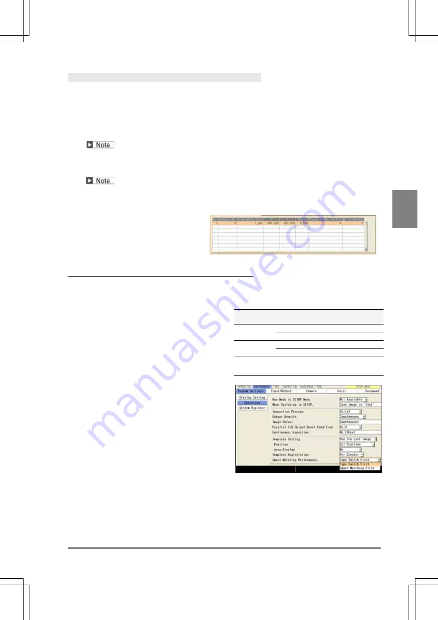
The list of detected objects is displayed in the lower part of the setting window. When selecting this
table and highlighting each No., the mark on the screen window indicating the detected area turns to
red.
-
The value of “255” in the “No. of Objects” column indicates the result exceeds 128.
Smart Matching Performance (Ver.1.20 or later)
This is the function that speeds up the processing of Smart Matching. The function takes more time of type
switch than without the function.
The function has the limit of the number of Smart
Matching ("Number of checkers" in the right table) to
allow speeding up the process. This number varies
depending on the settings of template size, inspection
sequence, rotation range, and angle step.
Check the processing time of inspection and type switch
on your actual device before you use the function.
Template
size
Rotation
range
Angle -
step
Number of
checkers*
128 x 128
±90
8
10
±180
8
6
384 x 384
±90
4
5
±180
4
3
*In the case of setting one template per Smart
Matching checker.
1.
Select "ENVIRONMENT" > “System Settings”
from the menu bar.
2.
Select "Operation".
3.
Select “Type Switch First" or "Smart Matching
First" in “Smart Matching Performance”.
Summary of Contents for PV-500
Page 1: ......
Page 10: ......
Page 11: ...9 Names and Descriptions Chapter 1 INDEX Chapter 1 Names and Descriptions ...
Page 21: ...19 Installation and Wiring Chapter 2 INDEX Chapter 2 Installation and Wiring ...
Page 37: ...35 Basic Operation Chapter 3 INDEX Chapter 3 Basic Operation ...
Page 55: ...53 Setting Inspection Conditions Chapter 4 INDEX Chapter 4 Setting Inspection Conditions ...
Page 345: ...343 Chapter 7 Changing Configuration INDEX Chapter 7 Changing Configuration TOOL ...
Page 375: ...373 Operation and Data Output through I O Terminals Chapter 8 INDEX ...
Page 390: ......
Page 391: ...389 Control with Communication Port Chapter 9 INDEX Chapter 9 Control with Communication Port ...
Page 430: ......
Page 431: ...429 PVWIN Chapter 10 INDEX Chapter 10 PVWIN ...
Page 493: ......
Page 494: ......


