123
Se
tt
ing I
n
s
p
e
c
tio
n C
on
d
it
ions
C
h
ap
te
r 4
INDE
X
5.
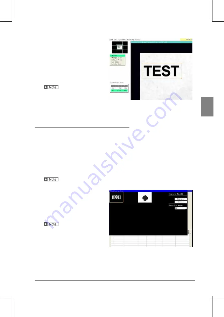
Select a shape of template area from
“Change Shape”.
Select from Rectangle, Ellipse, Circle and
Polygon.
6.
Select “Change” and set a template
area.
Refer to section of Drawing an Inspection
Area (page 47).
The maximum size to draw (the size of a
circumscribing rectangle of the area) is as
follow.
•
When using Quad-speed/Ultra Compact Camera: 640 x 480 pixels (full screen)
•
When using 2-Mega-pixel Camera: 1024 x 1024 pixels
If there is no feature (or the degree of change in gray level is low) within the specified area, the image
cannot be registered.
When you want to exclude an area from inspection
(Mask area)
Up to 16 mask areas, where is excluded from inspection (correlation calculation), can be set for a template.
Select "Add Mask" in template setting window, specify a shape and draw an area. Refer to section of Setting a
Mask Area (page 51) for details.
7.
Select “Output Point” and operate the ENTER key to specify an output point.
Output point is the point that indicates the location where the image resembling the template was detected.
You can place the output point at the desired location. (It can be set also outside template.)
While you are setting it, the coordinate of the current output point is displayed in the information display
area. Use it to make the setting.
Selecting “Middle Point” sets an output point in the center of a template from the pop-up menu displayed by
pressing the FUNC key.
8.
After setting is completed, press the
CANCEL key.
Return to the template setting window
.
To set multiple templates, select a
template No. and repeat the above
procedure.
If there is no feature (or the degree of
change in gray level is low) within the
specified area, a message will be
displayed and the template cannot be
registered.
From “Show this many:”, the number of displaying templates can be changed.
You can choose from the following as necessary; 16 (default), 4, and 1.
9.
After setting the template, press the CANCEL key.
The screen returns to “Smart Matching” setting window.
Summary of Contents for PV-500
Page 1: ......
Page 10: ......
Page 11: ...9 Names and Descriptions Chapter 1 INDEX Chapter 1 Names and Descriptions ...
Page 21: ...19 Installation and Wiring Chapter 2 INDEX Chapter 2 Installation and Wiring ...
Page 37: ...35 Basic Operation Chapter 3 INDEX Chapter 3 Basic Operation ...
Page 55: ...53 Setting Inspection Conditions Chapter 4 INDEX Chapter 4 Setting Inspection Conditions ...
Page 345: ...343 Chapter 7 Changing Configuration INDEX Chapter 7 Changing Configuration TOOL ...
Page 375: ...373 Operation and Data Output through I O Terminals Chapter 8 INDEX ...
Page 390: ......
Page 391: ...389 Control with Communication Port Chapter 9 INDEX Chapter 9 Control with Communication Port ...
Page 430: ......
Page 431: ...429 PVWIN Chapter 10 INDEX Chapter 10 PVWIN ...
Page 493: ......
Page 494: ......


