FUEL SYSTEM <DOHC>
models>
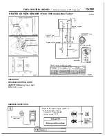
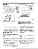
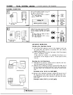
air
control motor
(stepper motor)
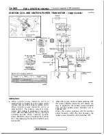
<From 1990 models>
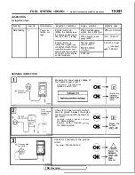
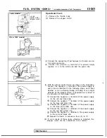
Operational Check
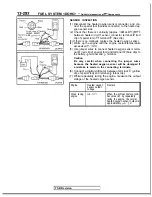
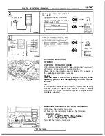
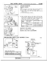
(1) Remove the throttle body.
(2) Remove the stepper motor
(3) Connect the special tool (Test harness) to the idle air con-
trol motor connector.
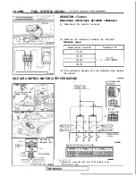
(4) Connect the positive
terminal of a power supply
(approx. 6 to the white clip and the green clip.
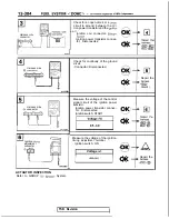
(5) With the idle air control motor as shown in the illustration,
connect the negative
terminal of the power supply to
each clip as described in the following steps, and check
whether or not a vibrating feeling (a feeling of very slight
vibration of the stepper motor) is generated as a result of
the activation of the stepper motor.
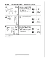
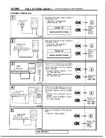
Connect the negative
terminal of the power supply
to the red and black clip.
Connect the negative
terminal of the power supply
to the blue and black clip.
Connect the negative
terminal of the power supply
to the blue and yellow clip.
Connect the negative
terminal of the power supply
to the red and yellow clip.
Connect the negative
terminal of the power supply
to the red and black clip.
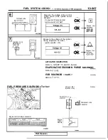
Repeat the tests in sequence from (5) to
(6) If, as a result of these tests, vibration is detected, the
stepper motor can be considered to be normal.
Revision
Summary of Contents for 1989 Galant
Page 2: ......
Page 4: ...00 z NOTES ...
Page 274: ...13 132 NOTE ...
Page 586: ...NOTES ...
Page 650: ...NOTE ...
Page 664: ...NOTES ...
Page 688: ...NOTES ...
Page 690: ......
Page 692: ......
Page 694: ......
Page 696: ......
Page 698: ......
Page 700: ...c ...
Page 702: ......
Page 704: ......
Page 706: ......
Page 708: ......
Page 710: ......
Page 712: ......
Page 714: ......
Page 716: ......
Page 718: ......
Page 720: ......
Page 722: ......
Page 724: ......
Page 729: ...23 23 NOTES ...
Page 860: ...NOTES ...
Page 921: ...NOTES ...
Page 948: ...33B 9 NOTES ...
Page 1121: ...NOTES ...
Page 1200: ...SERVICE BRAKES Brake Pedal 35 79 Lubrication points Part A 14AO256 1 14UOO5l TSB Revision ...
Page 1273: ...NOTES t ...

