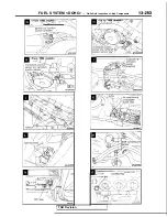
FUEL SYSTEM <DOHC>
On-Vehicle Inspection of
Components
COMPONENTS INSPECTION
Using Scan Tool
Refer to
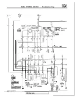
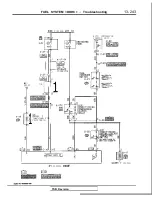
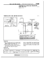
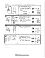
POWER SUPPLY AND IGNITION
injection relay
‘OWE
Ignition switch
Component
side
63 66
,
Harness
side connector
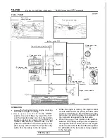
OPERATION
l
While the ignition switch is ON, battery power
supply is supplied to the engine control module,
injectors, volume air flow sensor, etc.
l
When the ignition switch is switched ON,
rent flows from the ignition switch, via the
fuel injection relay coil to ground.
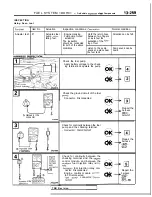
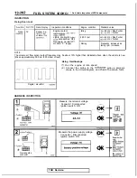
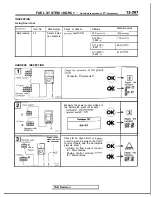
INSPECTION
Using Scan tool
As
a result,
the
fuel injection relay
switch is switched ON, and power is supplied,
by way of the
fuel injection relay
switch, from the battery to the engine control
module.
Function
Data reading
Item No.
Data display
Check conditions
Standard value
16
Engine control module power-
Ignition switch:
O N
Battery positive
voltage
supply voltage
TSB Revision
Summary of Contents for 1989 Galant
Page 2: ......
Page 4: ...00 z NOTES ...
Page 274: ...13 132 NOTE ...
Page 586: ...NOTES ...
Page 650: ...NOTE ...
Page 664: ...NOTES ...
Page 688: ...NOTES ...
Page 690: ......
Page 692: ......
Page 694: ......
Page 696: ......
Page 698: ......
Page 700: ...c ...
Page 702: ......
Page 704: ......
Page 706: ......
Page 708: ......
Page 710: ......
Page 712: ......
Page 714: ......
Page 716: ......
Page 718: ......
Page 720: ......
Page 722: ......
Page 724: ......
Page 729: ...23 23 NOTES ...
Page 860: ...NOTES ...
Page 921: ...NOTES ...
Page 948: ...33B 9 NOTES ...
Page 1121: ...NOTES ...
Page 1200: ...SERVICE BRAKES Brake Pedal 35 79 Lubrication points Part A 14AO256 1 14UOO5l TSB Revision ...
Page 1273: ...NOTES t ...

