


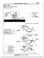
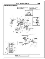

SERVICE BRAKES
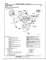
Brake Pedal
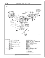
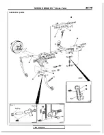
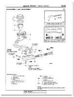
REMOVAL AND INSTALLATION
(Non-Turbo)>
steps
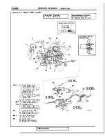
1. Stop light switch connector
<Vehicles with auto-cruise control
system>
2. Stop light switch connector
<Vehicles without auto-cruise control
7
Pre-removal Operation
*Removal of
Under Cover
(Refer to GROUP
Panel.)
@Removal of Steering Column Assembly
(Refer to GROUP
Wheel and
3. Stop light switch
<Vehicles with auto-cruise control
system>
4.
Stop light switch
<Vehicles without auto-cruise control
system>
5. Clutch pedal position switch connector
<Vehicles with auto-cruise control
system>
6.
switch connector
7. Return spring
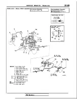
15. Cotter pin
Washer
17. Clevis pin
20. Pedal support bracket installation bolt and
nut
Clutch pedal bracket installation bolt and
Post-installation Operation
of Steering
Assembly
to GROUP
Wheel
of Instrument Under Cover
(Refer to GROUP
Panel.)
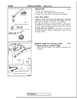
*Brake Pedal Adjustment
(Refer to
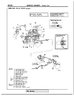
24. Interlock switch
25. Clutch pedal
29. Bushing
31. Pedal rod
32. Bushing
33. Brake pedal
nut
22. Pedal support bracket
NOTE
m o d e l s >
23. Clutch pedal bracket
<From 1990 models>
TSB Revision
Summary of Contents for 1989 Galant
Page 2: ......
Page 4: ...00 z NOTES ...
Page 274: ...13 132 NOTE ...
Page 586: ...NOTES ...
Page 650: ...NOTE ...
Page 664: ...NOTES ...
Page 688: ...NOTES ...
Page 690: ......
Page 692: ......
Page 694: ......
Page 696: ......
Page 698: ......
Page 700: ...c ...
Page 702: ......
Page 704: ......
Page 706: ......
Page 708: ......
Page 710: ......
Page 712: ......
Page 714: ......
Page 716: ......
Page 718: ......
Page 720: ......
Page 722: ......
Page 724: ......
Page 729: ...23 23 NOTES ...
Page 860: ...NOTES ...
Page 921: ...NOTES ...
Page 948: ...33B 9 NOTES ...
Page 1121: ...NOTES ...
Page 1200: ...SERVICE BRAKES Brake Pedal 35 79 Lubrication points Part A 14AO256 1 14UOO5l TSB Revision ...
Page 1273: ...NOTES t ...


