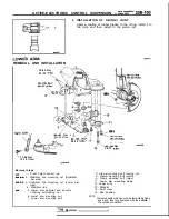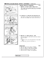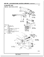
ACTIVE-ELECTRONIC CONTROL SUSPENSION
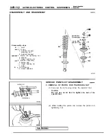
Assembly
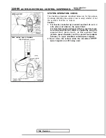
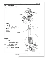
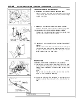
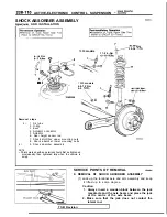
Strut
a
.
Front
Apply rubber grease
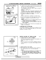
(3) Connect the air tube at the shut-off valve side of the
special tool (air-pressure gauge) to the air tube side, and
the other one to the strut assembly.
The installation at the strut side is done by using the
special tool (adaptor set).
Caution
To prevent the entry of moisture during the strut
assembly air leak check, utilize air from the dryer.
(4) Remove the compressor connector, then operate it by
connecting it directly to the battery.
NOTE
Refer to
for compressor connector array.
(5)
the strut assembly into a water tank and check for air
leakage at a pressure of about 500
(71 psi).
1. Don’t mistake the rise of bubbles attached to the
outside of the strut for air leakage.
2.
Dry the strut with an air blower after the check has
been completed.
(6) When air leakage is found, check the strut assembly and
replace it as necessary.
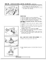
CHECKING THE ACTUATOR
For detailed information concerning the checking of the
actuator, refer to the troubleshooting guide and to the service
adjustment procedures section.
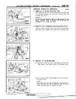
SERVICE POINTS OF INSTALLATION
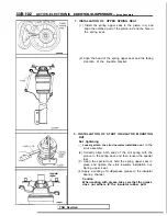
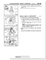
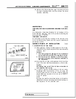
13. INSTALLATION OF STRUT ASSEMBLY
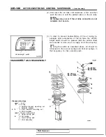
Install the strut assembly so that the strut insulator is in
the direction shown in the figure.
NOTE
Be sure to check to be sure that the installation direction is
correct, because if it is not the wheel alignment will be
incorrect.
2. INSTALLATION OF AIR TUBE
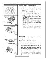
(1) After coating the O-ring with rubber grease, install the
ring, bush and flare nut to the strut assembly.
Caution
1. The O-ring may be damaged if it is installed at the
air tube side when the connection is made.
2. The bush must be installed so that the projection
part is facing in the direction indicated in the
illustration.
TSB Revision
Summary of Contents for 1989 Galant
Page 2: ......
Page 4: ...00 z NOTES ...
Page 274: ...13 132 NOTE ...
Page 586: ...NOTES ...
Page 650: ...NOTE ...
Page 664: ...NOTES ...
Page 688: ...NOTES ...
Page 690: ......
Page 692: ......
Page 694: ......
Page 696: ......
Page 698: ......
Page 700: ...c ...
Page 702: ......
Page 704: ......
Page 706: ......
Page 708: ......
Page 710: ......
Page 712: ......
Page 714: ......
Page 716: ......
Page 718: ......
Page 720: ......
Page 722: ......
Page 724: ......
Page 729: ...23 23 NOTES ...
Page 860: ...NOTES ...
Page 921: ...NOTES ...
Page 948: ...33B 9 NOTES ...
Page 1121: ...NOTES ...
Page 1200: ...SERVICE BRAKES Brake Pedal 35 79 Lubrication points Part A 14AO256 1 14UOO5l TSB Revision ...
Page 1273: ...NOTES t ...

