

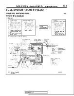


FUEL SYSTEM
VALVE>
Troubleshooting
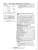
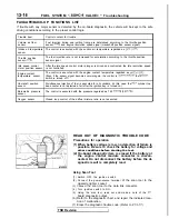
ON-BOARD
The engine control
module monitors the input/out-
put signals (some signals at all times and the others
under specified conditions) of the engine control
module.
When it is noticed that an irregularity has continued
for a specified time or longer from when the irregu-
lar signal is initially monitored, passing a certain
number, the engine control module judges that an
irregularity has occurred, memorizes the diagnostic
trouble code, and outputs the signal to the on-board
diagnostic output terminal.
There are 15 on-board diagnostic items including
the normal state, and the diagnostic results can be
read out with a voltmeter or scan tool.
Moreover, since memorization of the diagnostic
trouble codes is backed up directly by the battery,
the diagnostic results are memorized even if the ig-
nition key is turned off. The diagnostic trouble
codes will, however, be erased when the battery
disconnected. In addition, beginning with the engine
control module of
and later models, the diag-
nostic trouble codes are erased by turning on the
ignition switch and sending the diagnostic trouble
code erase signal from the scan tool to the engine
control module.
Caution
If the sensor connector is disconnected with
the ignition switch turned on, the diagnostic
trouble code is memorized. In this case, send
the diagnostic trouble code erase signal from
the scan tool to the engine control module or
disconnect the battery terminal
for 10 sec-
onds or more, and the diagnostic memory will
be erased.
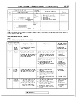
The 15 on-board diagnostic items are provided as
follows, and if plural items are activated, they are all
indicated sequentially from the smallest code
I---
terminal or the engine control module connector is
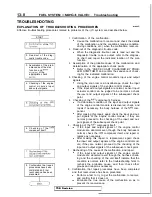
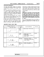
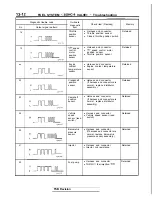
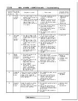
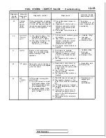
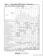
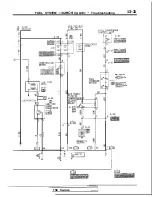
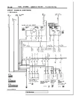
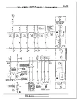
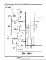
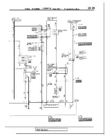
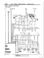
DIAGNOSTIC CHART (FAULT TREE)
No.
Diagnostic trouble code
On-board
diagnostic
Check
item (Remedy)
Memory
Output signal pattern
item
Engine
(Replace engine control module)
control
module
Oxygen
l
Harness and connector
Retained
sensor
Oxygen sensor
. Fuel pressure
l
Injectors (Replace if defective.)
l
Intake air leaks
12
Volume air
l
Harness and connector
Retained
flow sensor
(if harness and connector are
normal, replace volume air flow
sensor assembly.)
13
Intake air
l
Harness and connector
Retained
temperature
l
Intake air temperature sensor
sensor
TSB Revision
Summary of Contents for 1989 Galant
Page 2: ......
Page 4: ...00 z NOTES ...
Page 274: ...13 132 NOTE ...
Page 586: ...NOTES ...
Page 650: ...NOTE ...
Page 664: ...NOTES ...
Page 688: ...NOTES ...
Page 690: ......
Page 692: ......
Page 694: ......
Page 696: ......
Page 698: ......
Page 700: ...c ...
Page 702: ......
Page 704: ......
Page 706: ......
Page 708: ......
Page 710: ......
Page 712: ......
Page 714: ......
Page 716: ......
Page 718: ......
Page 720: ......
Page 722: ......
Page 724: ......
Page 729: ...23 23 NOTES ...
Page 860: ...NOTES ...
Page 921: ...NOTES ...
Page 948: ...33B 9 NOTES ...
Page 1121: ...NOTES ...
Page 1200: ...SERVICE BRAKES Brake Pedal 35 79 Lubrication points Part A 14AO256 1 14UOO5l TSB Revision ...
Page 1273: ...NOTES t ...


