FUEL SYSTEM <DOHC> Service Adjustment Procedures
T V = = = - -
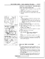
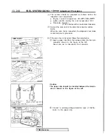
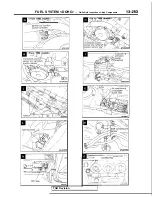
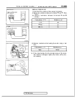
(5) If there is a deviation from the standard value, loosen the
throttle-position sensor installation bolt and then turn the
throttle-position sensor itself to make the adjustment after
the throttle body was removed. Be sure to securely
retighten the bolt after making the adjustment.
NOTE
The output voltage becomes higher when the
position sensor is turned clockwise.
For removal and installation of throttle body, refer to
“Engine Service Manual”.
I
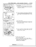
<From 1990 models>
I
Closed throttle
position switch
connector
(6) Switch OFF the ignition switch.
(7) If the diagnostic trouble code is output while adjusting the
throttle position sensor, use a scan tool to erase the diag-
nostic trouble code, or disconnect the battery cable from
the negative terminal of the battery for more than
sec-
onds and then reconnect the cable. (This will cancel the
memory of the failure code due to throttle position sensor
adjustment.)
CLOSED THROTTLE POSITION SWITCH (FIXED
SAS) ADJUSTMENT
NOTE
1. The closed throttle position switch has been precisely ad-
justed by the manufacturer; it should not, therefore, be
moved to another setting.
2. If however, the adjustment is for any reason accidentally
disturbed, or the closed throttle position switch is replaced,
make the necessary readjustment by following the
steps
(1)
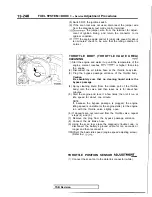
relax the tension of the accelerator cable.
(2) Disconnect the connector of the closed throttle position
switch (fixed SAS).
(3) Loosen the lock nut of the closed throttle position switch
(fixed SAS).
(4) Turn the closed throttle position switch (fixed SAS) in the
counter-clockwise direction until it is sufficiently loosened,
and securely close the throttle valve fully.
(5) Connect an ohmmeter between the closed throttle position
switch terminal and the body.
(6) Begin tightening the closed throttle position switch and lo-
cate the point at which the closed throttle position switch
is switched ON (conductive with body). (This is the point at
which the throttle valve begins to open.) From that point,
then tighten the closed throttle position switch
turn.
(7) Securely tighten the lock nut while holding the closed
throttle position switch so that it won’t turn.
(8) Adjust the tension of the accelerator cable.
(9) Adjust the basic idling speed (engine speed adjusting
screw).
the throttle-position sensor.
TSB Revision
Summary of Contents for 1989 Galant
Page 2: ......
Page 4: ...00 z NOTES ...
Page 274: ...13 132 NOTE ...
Page 586: ...NOTES ...
Page 650: ...NOTE ...
Page 664: ...NOTES ...
Page 688: ...NOTES ...
Page 690: ......
Page 692: ......
Page 694: ......
Page 696: ......
Page 698: ......
Page 700: ...c ...
Page 702: ......
Page 704: ......
Page 706: ......
Page 708: ......
Page 710: ......
Page 712: ......
Page 714: ......
Page 716: ......
Page 718: ......
Page 720: ......
Page 722: ......
Page 724: ......
Page 729: ...23 23 NOTES ...
Page 860: ...NOTES ...
Page 921: ...NOTES ...
Page 948: ...33B 9 NOTES ...
Page 1121: ...NOTES ...
Page 1200: ...SERVICE BRAKES Brake Pedal 35 79 Lubrication points Part A 14AO256 1 14UOO5l TSB Revision ...
Page 1273: ...NOTES t ...

