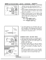
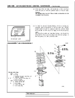


ACTIVE-ELECTRONIC CONTROL SUSPENSION
O
-
r
i
n
g
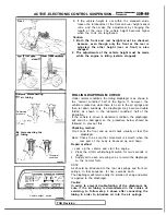
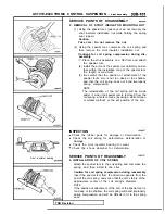
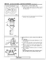
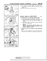
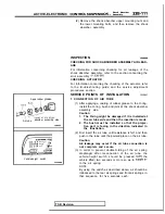
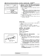
2. INSTALLATION OF O-RING/l. JOINT
Apply a coating of rubber grease to the O-ring, install it to
the joint, and then install to the piston rod.
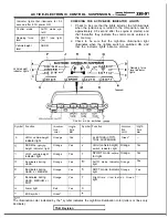
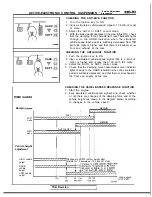
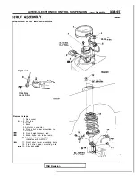
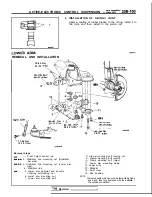
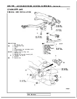
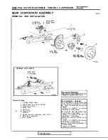
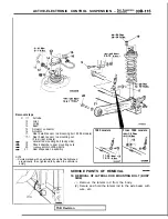
REMOVAL AND INSTALLATION
.
35-45 Nm
25-33
Nm
1 7 '
58-72
- -
Nm
58-72
17-26 Nm
12-18
Removal steps
Front height sensor rod
2. Stabilizer link mounting nut (Stabilizer
bar side)
3. Stabilizer link mounting nut (Lower arm
side)
4. Stabilizer link
5. Lower arm ball-joint and knuckle
coupling self-locking nut
6. Lower arm mounting nut
7. Lower arm mounting bolt
Clamp mounting self locking nut
9. Clamp mounting bolt (small)
Clamp mounting bolt (large)
11. Lower arm mounting clamp
12. Lower
arm
13. Stopper
14. Dust cover
15. Rod bushing
NOTE
Indicates parts which should be temporarily tight-
ened, and then fully tightened with the
vehicle
the unladen condition.
Revision
I
Summary of Contents for 1989 Galant
Page 2: ......
Page 4: ...00 z NOTES ...
Page 274: ...13 132 NOTE ...
Page 586: ...NOTES ...
Page 650: ...NOTE ...
Page 664: ...NOTES ...
Page 688: ...NOTES ...
Page 690: ......
Page 692: ......
Page 694: ......
Page 696: ......
Page 698: ......
Page 700: ...c ...
Page 702: ......
Page 704: ......
Page 706: ......
Page 708: ......
Page 710: ......
Page 712: ......
Page 714: ......
Page 716: ......
Page 718: ......
Page 720: ......
Page 722: ......
Page 724: ......
Page 729: ...23 23 NOTES ...
Page 860: ...NOTES ...
Page 921: ...NOTES ...
Page 948: ...33B 9 NOTES ...
Page 1121: ...NOTES ...
Page 1200: ...SERVICE BRAKES Brake Pedal 35 79 Lubrication points Part A 14AO256 1 14UOO5l TSB Revision ...
Page 1273: ...NOTES t ...


