


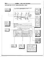


GENERAL How to Use This Manual
and gear box connecting
return tube
3
for
hose
4
cotter
end and knuckle connecting
I
10. Center member rear
Front exhaust
12. Gear
assembly
. .
rubber
Denotes non-re-
p
u
s
a
b
l
e
p
a
r
t
.
- 6
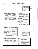
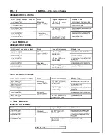
Repair kit or set parts are shown.
(Only very frequently used parts
Operating procedures, cautions,
I
I
etc. on removal, installation,
[scribed, ,
assembly and reassembly are
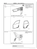
STEERING
6.
OF
END
Using the
the tie
from the
knuckle.
1 .
2.
12. REMOVAL OF GEAR BOX
number corresponds to the
steps”,
s t e p s ” o r
steps”.
AND
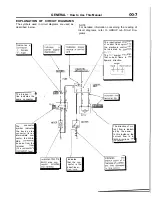
The title of the page
the page on which the diagram of
component parts is presented)
indicating the locations of
tion and sealing procedures.
Summary of Contents for 1989 Galant
Page 2: ......
Page 4: ...00 z NOTES ...
Page 274: ...13 132 NOTE ...
Page 586: ...NOTES ...
Page 650: ...NOTE ...
Page 664: ...NOTES ...
Page 688: ...NOTES ...
Page 690: ......
Page 692: ......
Page 694: ......
Page 696: ......
Page 698: ......
Page 700: ...c ...
Page 702: ......
Page 704: ......
Page 706: ......
Page 708: ......
Page 710: ......
Page 712: ......
Page 714: ......
Page 716: ......
Page 718: ......
Page 720: ......
Page 722: ......
Page 724: ......
Page 729: ...23 23 NOTES ...
Page 860: ...NOTES ...
Page 921: ...NOTES ...
Page 948: ...33B 9 NOTES ...
Page 1121: ...NOTES ...
Page 1200: ...SERVICE BRAKES Brake Pedal 35 79 Lubrication points Part A 14AO256 1 14UOO5l TSB Revision ...
Page 1273: ...NOTES t ...


