
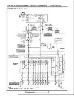


ACTIVE-ELECTRONIC CONTROL SUSPENSION Troubleshooting
Diagnostic
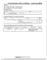
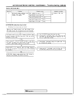
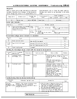
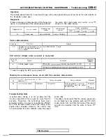
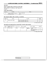
When a signal (error code) indicating an abnormal
condition (resulting from damage or disconnection
of the heavy-line circuit, or a malfunction of a
photo-transistor, etc.) is input, the alarm light
minates and control is as described in the table
below.
Diagnostic No.
Attitude control
Damping force
V e h i c l e - h e i g h t
Switch acceptance
control
control
HIGH
SPORT
AUTO
SOFT
22
Control stop
Held at MEDIUM
Control stop
Not accept
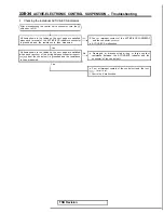
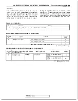
Service data indication
Code No
Indication example
22
Current vehicle-height level (ERROR
When
1111
when there is a malfunction)
normal
the ON or OFF status of
the vehicle-height
of each photo-interruptor
level.
1:
OFF
each
If
22; ERROR
function
Indicates that an error code is
Status of each photo-interruptor
beina output.
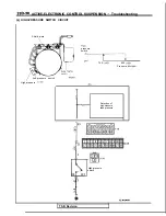
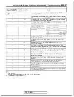
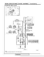
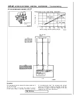
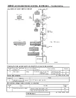
ECU terminal voltages (when connector is connected)
No
Condition
Terminal
25
56.57
Power source for sensor
Front
signal
When the ECU is activated
When the
are ON
o v
When the photo-interruptors are OFF
36
Sensor circuit ground
I Constantlv
I
o v
I
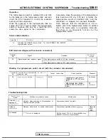
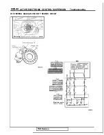
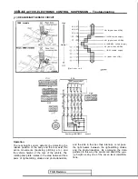
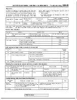
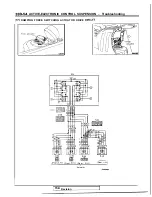
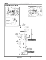
Checking the front-height sensor circuit (with the connector disconnected)
Terminal
destination
No
measured part
Front-height sensor
power-supply
56
57
Front-height sensor
Resistance
Measurement
Resistance
25-36
Tester connection
54-36
55-36
56-36
57-36
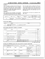
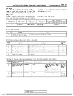
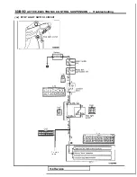
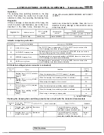
Troubleshooting hints (mechanical malfunctions)
Check condition
Standard
Contact the tester’s
probe to
terminal 25, and the probe to
(The
terminal 36.
Note
fluctuates)
Even if the result is good here,
the sensor must not be judged
be certainly good.
Contact the tester’s
probe to
terminal 25, and the
probe to
terminal 36, and check to be sure
that there is continuity, leave the
connections as they are.
Connect the tester’s
probe to
each terminal of the wiring
harness connector, and the
probe to terminal 36
Separate the lever (of the height
sensor) from the rod, and
slowly
the lever up and down.
No
I
Continuity
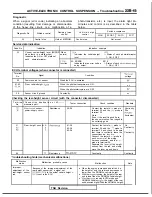
Malfunction
mode
Malfunction probable cause
Malfunction
Note
Improper
Because of the improper adjustment of the
adjustment of the
front-height sensor
front-height sensor rod, a signal not
l
When the engine is stopped and left as it is,
corresponding to the actual vehicle
height is
the height of
front end decreases to
rod
being sent to the ECU
lower than the NORMAL vehicle height
l
With the
running, the height of the front
end
IS
lower than the NORMAL
l
With the engine running (AUTO mode and
the height of the front
end becomes higher than the NORMAL
TSB Revision
I
Summary of Contents for 1989 Galant
Page 2: ......
Page 4: ...00 z NOTES ...
Page 274: ...13 132 NOTE ...
Page 586: ...NOTES ...
Page 650: ...NOTE ...
Page 664: ...NOTES ...
Page 688: ...NOTES ...
Page 690: ......
Page 692: ......
Page 694: ......
Page 696: ......
Page 698: ......
Page 700: ...c ...
Page 702: ......
Page 704: ......
Page 706: ......
Page 708: ......
Page 710: ......
Page 712: ......
Page 714: ......
Page 716: ......
Page 718: ......
Page 720: ......
Page 722: ......
Page 724: ......
Page 729: ...23 23 NOTES ...
Page 860: ...NOTES ...
Page 921: ...NOTES ...
Page 948: ...33B 9 NOTES ...
Page 1121: ...NOTES ...
Page 1200: ...SERVICE BRAKES Brake Pedal 35 79 Lubrication points Part A 14AO256 1 14UOO5l TSB Revision ...
Page 1273: ...NOTES t ...


