


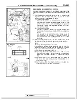

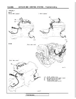
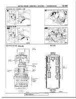
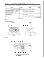
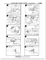


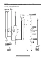
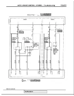

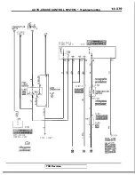

AUTO-CRUISE CONTROL SYSTEM Troubleshooting
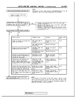
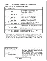
INPUT CHECK TABLE
Code
Display patterns (output codes)
Input operation
Check results
No.
(use with voltmeter)
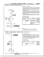
21
SET switch ON
switch circuit
RESUME switch ON
RESUME switch circuit
normal
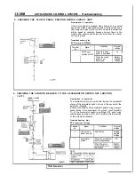
23
<Electrical type>
<Electrical type>
Each cancel switch ON
Each cancel circuit
1. Stop light switch (brake pedal
depressed)
<Vacuum type>
2. Clutch pedal position switch
(clutch pedal depressed)
light switch
< M / T >
3. Park/neutral position switch
(shift lever to
range)
< A / T >
<Vacuum type>
Stop light switch ON (brake pedal
depressed)
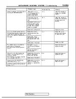
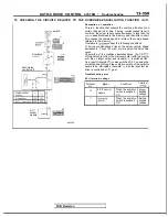
24
25
Driving at approximately to 40
When both
and
km/h (25 mph) or higher
can be confirmed,
vehicle-speed sensor
circuit normal.
Driving at less than approximately
to 40 km/h (25 mph) or stopped
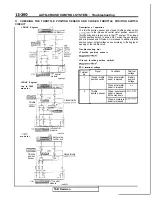
26
Clutch pedal position switch
pedal depressed)
2. Park/Neutral position switch
ON (shift lever to “N” or “P”
range)
Clutch pedal position
switch, park/neutral
position switch normal
28
Throttle position sensor output
voltage over
(when the ac-
celerator pedal is pressed more
than half way)
position sensor
Closed throttle position switch
Closed throttle position
OFF (accelerator pedal depressed)
switch normal
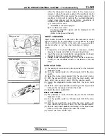
NOTE
1. Each code will be displayed in an order of priority beginning from No. 1.
If there is no display, it is possible that there is a malfunction of the ECU power-supply circuit or the SET and/or
RESUME switch, so check according to check charts 1.2 and 3
2. Continue each input operation until the output code is emitted.
If no output codes are emitted for inputs even though the display pattern is repeated two or more times, there is a
malfunction of the switch sensor.
3.
When each input operation is performed and the signals for the conditions are received by the computer, each
output code will be repeatedly displayed in the sequence of priority for as long as that signal continues.
4.
If, during the display of output codes, the input operation is canceled (if, for example, the SET
is set from ON
to OFF), the code will be displayed for one cycle of the display, but will not be displayed during the next cycle.
This makes it possible, therefore, to check the OFF condition (existence of not of a short-circuit of the input line or
the switch).
TSB Revision
Summary of Contents for 1989 Galant
Page 2: ......
Page 4: ...00 z NOTES ...
Page 274: ...13 132 NOTE ...
Page 586: ...NOTES ...
Page 650: ...NOTE ...
Page 664: ...NOTES ...
Page 688: ...NOTES ...
Page 690: ......
Page 692: ......
Page 694: ......
Page 696: ......
Page 698: ......
Page 700: ...c ...
Page 702: ......
Page 704: ......
Page 706: ......
Page 708: ......
Page 710: ......
Page 712: ......
Page 714: ......
Page 716: ......
Page 718: ......
Page 720: ......
Page 722: ......
Page 724: ......
Page 729: ...23 23 NOTES ...
Page 860: ...NOTES ...
Page 921: ...NOTES ...
Page 948: ...33B 9 NOTES ...
Page 1121: ...NOTES ...
Page 1200: ...SERVICE BRAKES Brake Pedal 35 79 Lubrication points Part A 14AO256 1 14UOO5l TSB Revision ...
Page 1273: ...NOTES t ...


