SERVICE BRAKES
Hydraulic Unit <Vehicles with
35-121
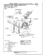
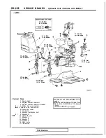
HYDRAULIC UNIT <VEHICLES WITH
AND INSTALLATION
<Up
to 1991 models>
Flared brake line nuts
1 3 - 1 7
9 - 1 4
6
1 7 - 2 6
1 2 - 1 9
1 7 - 2 6
1 2 - 1 9
1 7 - 2 6
1 2 - 1 9
Removal Steps
1. Dust shield
2. Engine coolant reservoir
3. Engine coolant reservoir bracket
4. Brake hose connection
5. Brake tube connection
6. Relay box cover
7. Connector
8. Bracket installation bolt
l
+ 9. Bracket A
Hydraulic unit
11. Bracket
12. Bracket
13. Bracket
16. Motor relay
17. Valve relay
and Post-installation
l
Draining and Supplying of Brake
l
Removai and Installation of the
1 7 - 2 6
Revision
Summary of Contents for 1989 Galant
Page 2: ......
Page 4: ...00 z NOTES ...
Page 274: ...13 132 NOTE ...
Page 586: ...NOTES ...
Page 650: ...NOTE ...
Page 664: ...NOTES ...
Page 688: ...NOTES ...
Page 690: ......
Page 692: ......
Page 694: ......
Page 696: ......
Page 698: ......
Page 700: ...c ...
Page 702: ......
Page 704: ......
Page 706: ......
Page 708: ......
Page 710: ......
Page 712: ......
Page 714: ......
Page 716: ......
Page 718: ......
Page 720: ......
Page 722: ......
Page 724: ......
Page 729: ...23 23 NOTES ...
Page 860: ...NOTES ...
Page 921: ...NOTES ...
Page 948: ...33B 9 NOTES ...
Page 1121: ...NOTES ...
Page 1200: ...SERVICE BRAKES Brake Pedal 35 79 Lubrication points Part A 14AO256 1 14UOO5l TSB Revision ...
Page 1273: ...NOTES t ...

