SERVICE BRAKES
Service Adjustment Procedures
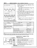
When turned manually
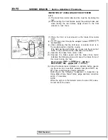
POINTS IN WAVEFORM MEASUREMENT
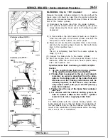
3. Manually turning the wheel to be measured by
to 1
turn/second, measure the output voltage with a circuit
tester or oscilloscope.
Output voltage:
When measured with circuit tester: 70
or more
When measured with oscilloscope (max. voltage): 100
or more
Probable causes of low output voltage
Speed sensor pole piece-to-rotor clearance too large
l
Faulty speed sensor
4. Then, in order to observe the output state of the wheel
speed sensors, shift into low gear
vehicle) and drive
the wheels, observe the output voltage waveform of each
wheel speed sensor with an oscilloscope.
In the case of the FWD vehicle, observe the waveform with
an oscilloscope; for the front wheels, shift into low gear and
drive the wheels; for the rear wheels, turn the wheels
manually at a constant speed.
NOTE
1.
Waveform may also be observed by actually driving the
vehicle.
2.
The output voltage is low when the wheel speed is low
and increases as the wheel speed increases.
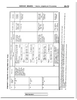
Symptom
Too small or zero waveform
amplitude
Probable causes
Faulty wheel speed sensor
Remedy
Replace sensor
Incorrect pole piece-to-rotor clearance
Adjust clearance
Waveform amplitude fluctuates
Axle hub eccentric or with large
Replace hub
excessively (this is no problem if
the minimum amplitude is 100
or more)
Noisy or disturbed waveform
Open circuit in sensor
Replace sensor
Open circuit in harness
Correct harness
Incorrectly mounted wheel speed sensor
Mount correctly
Rotor with missing or damaged teeth
Replace rotor
NOTE
The wheel speed sensor cable moves following motion of the front or rear suspension. Therefore, it is likely that it has an
open circuit only when driving on rough roads and it functions normally on
roads. It is, therefore, recommended
to observe sensor output voltage waveform also under special conditions, such as rough road
TSB Revision
INSPECTION OF HYDRAULIC UNIT
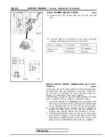
INSPECTION BY FEEL
(1) Jack up the vehicle and support the vehicle with rigid racks
placed at the specified jack-up points.
Release the parking brake and determine the drag force
(drag torque) of each wheel by feel.
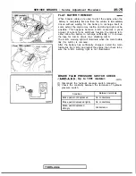
(3) Set the scan tool through the adapter harness
377)
as illustrated.
(4) After confirming that the shift lever or selector lever is in
the neutral position, start the engine.
The ABS warning light lights up, it goes into the scan tool
mode. In the scan tool mode, ABS does not function.
I
Summary of Contents for 1989 Galant
Page 2: ......
Page 4: ...00 z NOTES ...
Page 274: ...13 132 NOTE ...
Page 586: ...NOTES ...
Page 650: ...NOTE ...
Page 664: ...NOTES ...
Page 688: ...NOTES ...
Page 690: ......
Page 692: ......
Page 694: ......
Page 696: ......
Page 698: ......
Page 700: ...c ...
Page 702: ......
Page 704: ......
Page 706: ......
Page 708: ......
Page 710: ......
Page 712: ......
Page 714: ......
Page 716: ......
Page 718: ......
Page 720: ......
Page 722: ......
Page 724: ......
Page 729: ...23 23 NOTES ...
Page 860: ...NOTES ...
Page 921: ...NOTES ...
Page 948: ...33B 9 NOTES ...
Page 1121: ...NOTES ...
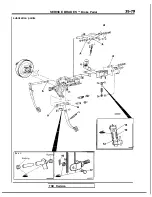
Page 1200: ...SERVICE BRAKES Brake Pedal 35 79 Lubrication points Part A 14AO256 1 14UOO5l TSB Revision ...
Page 1273: ...NOTES t ...


