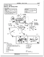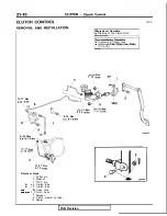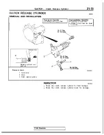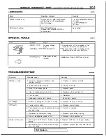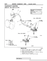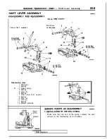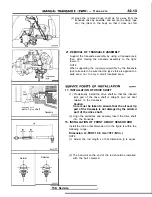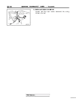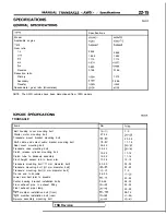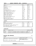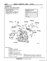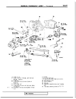
Removal
steps
Cotter pin
2.
Retainer
3. Retainer
4. Cotter pin
l
* 5. Shift cable
l
+ 6.
Select cable
7. Shift lever assembly
Pre-removal and Post-installation
Operation
*Removal and Installation of Console I
t o
<From 1991
l
Check the select cable for function and for damage.
l
Check the shift cable for function and for damage.
l
Check the boot for damage.
l
Check each bushing for wear or abrasion, sticking,
impeded action, and damage.
l
Check the spring for deteriorated strength.
TSB Revision
Summary of Contents for 1989 Galant
Page 2: ......
Page 4: ...00 z NOTES ...
Page 274: ...13 132 NOTE ...
Page 586: ...NOTES ...
Page 650: ...NOTE ...
Page 664: ...NOTES ...
Page 688: ...NOTES ...
Page 690: ......
Page 692: ......
Page 694: ......
Page 696: ......
Page 698: ......
Page 700: ...c ...
Page 702: ......
Page 704: ......
Page 706: ......
Page 708: ......
Page 710: ......
Page 712: ......
Page 714: ......
Page 716: ......
Page 718: ......
Page 720: ......
Page 722: ......
Page 724: ......
Page 729: ...23 23 NOTES ...
Page 860: ...NOTES ...
Page 921: ...NOTES ...
Page 948: ...33B 9 NOTES ...
Page 1121: ...NOTES ...
Page 1200: ...SERVICE BRAKES Brake Pedal 35 79 Lubrication points Part A 14AO256 1 14UOO5l TSB Revision ...
Page 1273: ...NOTES t ...

