


FUEL SYSTEM
VALVE>
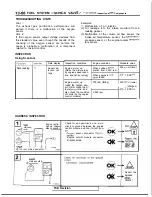
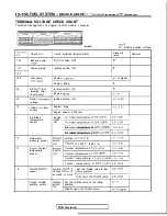
Inspection of
Components
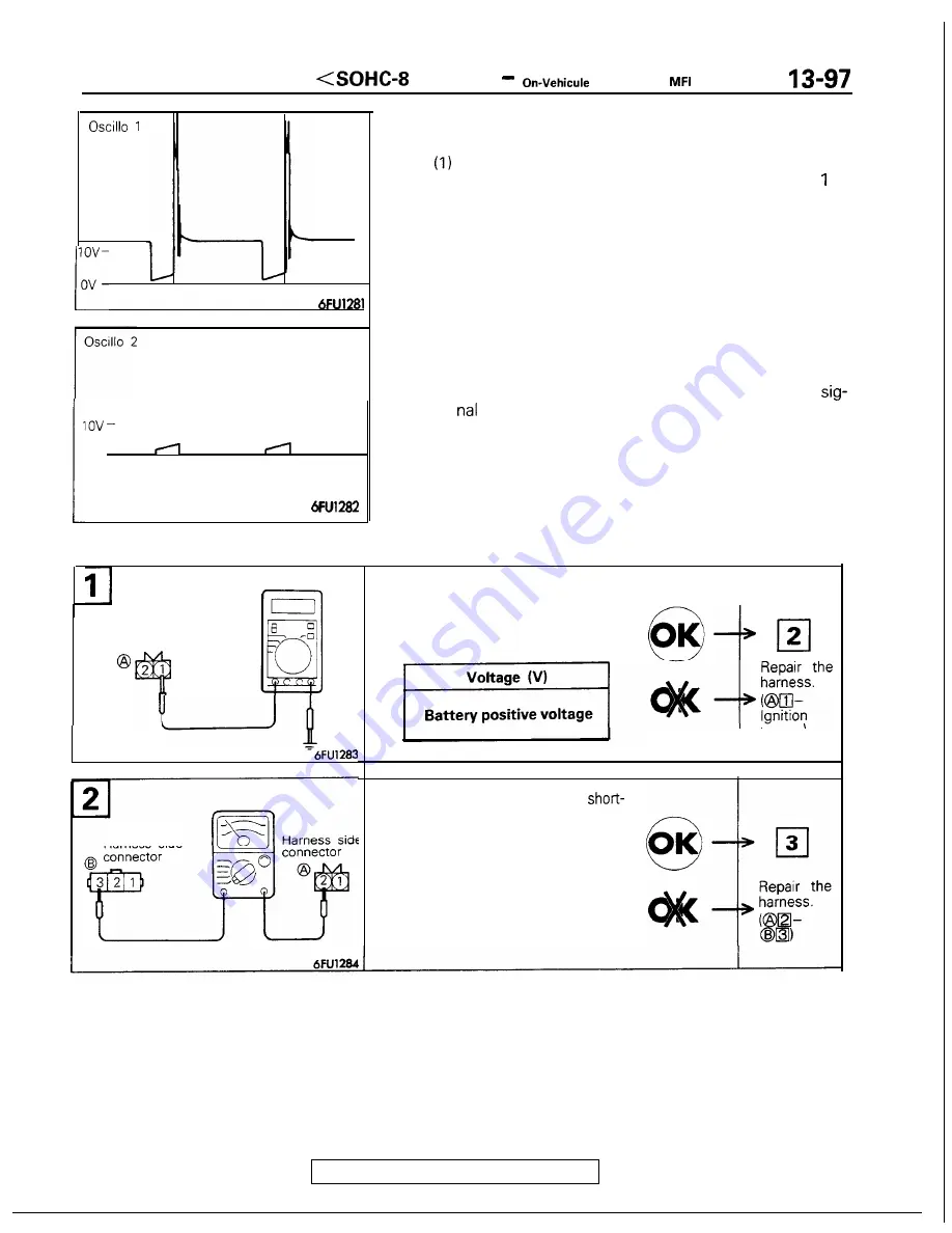
N o r m a l w a v e f o r m
ov
of the ignition power transistor,
Normal waveform
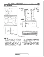
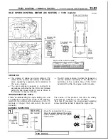
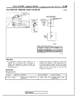
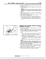
Using Oscilloscope
1. Primary signal of ignition coil
Run the engine at an idle revolution speed.
(2) Connect the probe to oscilloscope pick-up point as
shown in the circuit diagram, and check the primary
signal of the ignition coil.
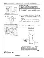
2.
Control signal of ignition power transistor
(1) Connect
the probe to oscilloscope pick-up point 2 as
shown in the circuit diagram, and check the control
Harness side
connector
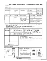
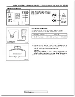
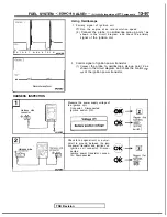
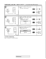
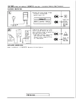
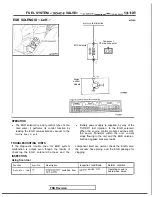
HARNESS INSPECTION
I
I
I
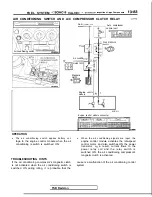
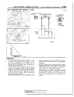
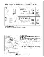
Measure the power supply voltage of
the ignition coil.
. Connector: Disconnected
. Ignition switch: ON
OK
TSB Revision
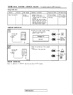
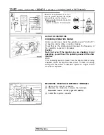
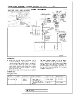
Harness side
switch)
Check for an open-circuit, or a
circuit to ground, between the igni-
tion power transistor and ignition coil.
. Ignition coil connector: Discon-
nected
. Ignition power transistor connec-
tor: Disconnected
Summary of Contents for 1989 Galant
Page 2: ......
Page 4: ...00 z NOTES ...
Page 274: ...13 132 NOTE ...
Page 586: ...NOTES ...
Page 650: ...NOTE ...
Page 664: ...NOTES ...
Page 688: ...NOTES ...
Page 690: ......
Page 692: ......
Page 694: ......
Page 696: ......
Page 698: ......
Page 700: ...c ...
Page 702: ......
Page 704: ......
Page 706: ......
Page 708: ......
Page 710: ......
Page 712: ......
Page 714: ......
Page 716: ......
Page 718: ......
Page 720: ......
Page 722: ......
Page 724: ......
Page 729: ...23 23 NOTES ...
Page 860: ...NOTES ...
Page 921: ...NOTES ...
Page 948: ...33B 9 NOTES ...
Page 1121: ...NOTES ...
Page 1200: ...SERVICE BRAKES Brake Pedal 35 79 Lubrication points Part A 14AO256 1 14UOO5l TSB Revision ...
Page 1273: ...NOTES t ...


