


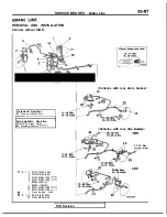
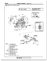

SERVICE BRAKES
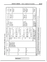
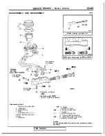
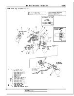
Brake Pedal
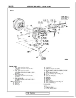
(Turbo)>
6 ’
Removal steps
2. Stop light switch connector
4. Stop light switch
5. Clutch pedal position switch
6. Interlock switch connector
7. Return spring
8. Cotter pin
9. Washer
Busing
11. Clevis pin
12.
spring
15. Cotter pin
16. Washer
17. Clevis pin
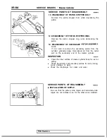
20. Pedal support bracket installation bolt and
nut
21. Clutch pedal bracket installation bolt and
nut
22. Pedal support bracket
23. Clutch pedal bracket
Pre-removal Operation
of Instrument Under Cover
(Refer to GROUP
Panel.)
l
Removal of Steering Column, Assembly
to GROUP
Wheel
and
I
Post-installation Operation
l
installation of Steering Column Assembly
to GROUP
Wheel and
of Instrument Under Cover
(Refer to GROUP
Panel.)
l
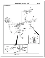
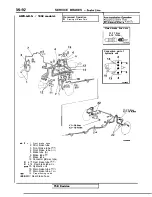
Brake Pedal
(Refer to
24. Interlock switch
25. Clutch pedal
29. Bushing
Pedal rod
32. Bushing
33. Brake pedal
TSB
Revision
Summary of Contents for 1989 Galant
Page 2: ......
Page 4: ...00 z NOTES ...
Page 274: ...13 132 NOTE ...
Page 586: ...NOTES ...
Page 650: ...NOTE ...
Page 664: ...NOTES ...
Page 688: ...NOTES ...
Page 690: ......
Page 692: ......
Page 694: ......
Page 696: ......
Page 698: ......
Page 700: ...c ...
Page 702: ......
Page 704: ......
Page 706: ......
Page 708: ......
Page 710: ......
Page 712: ......
Page 714: ......
Page 716: ......
Page 718: ......
Page 720: ......
Page 722: ......
Page 724: ......
Page 729: ...23 23 NOTES ...
Page 860: ...NOTES ...
Page 921: ...NOTES ...
Page 948: ...33B 9 NOTES ...
Page 1121: ...NOTES ...
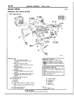
Page 1200: ...SERVICE BRAKES Brake Pedal 35 79 Lubrication points Part A 14AO256 1 14UOO5l TSB Revision ...
Page 1273: ...NOTES t ...