

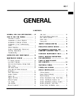


GENERAL
How to Use This Manual
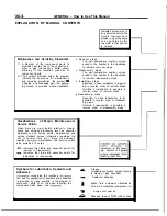
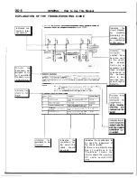
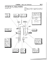
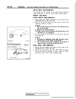
EXPLANATION OF CIRCUIT DIAGRAMS
The symbols used in circuit diagrams are used as
NOTE
described below.
For detailed information concerning the reading of
, circuit diagrams, refer to GROUP
Dia-
grams.
I n d i c a t e s a
The input/output
of current flow)
the electronic control
is indicated by
The
symbol
that current flows in
upward direction.
output
The broken
line indicates the
t
-
/
r
same connector.
The
connector
symbol indicates
the device side
connector (for an
intermediate con-
nector, the
male
side
as seen from the
terminal
fronl
( t h e
face).
RELAY
side con-
MOTOR
Indicates
that the con-
nector is the
direct-inser-
tion
The direction of
reht flow is indicat-
ed by the arrow.
In this instance, the
current flow is in
both directions.
Summary of Contents for 1989 Galant
Page 2: ......
Page 4: ...00 z NOTES ...
Page 274: ...13 132 NOTE ...
Page 586: ...NOTES ...
Page 650: ...NOTE ...
Page 664: ...NOTES ...
Page 688: ...NOTES ...
Page 690: ......
Page 692: ......
Page 694: ......
Page 696: ......
Page 698: ......
Page 700: ...c ...
Page 702: ......
Page 704: ......
Page 706: ......
Page 708: ......
Page 710: ......
Page 712: ......
Page 714: ......
Page 716: ......
Page 718: ......
Page 720: ......
Page 722: ......
Page 724: ......
Page 729: ...23 23 NOTES ...
Page 860: ...NOTES ...
Page 921: ...NOTES ...
Page 948: ...33B 9 NOTES ...
Page 1121: ...NOTES ...
Page 1200: ...SERVICE BRAKES Brake Pedal 35 79 Lubrication points Part A 14AO256 1 14UOO5l TSB Revision ...
Page 1273: ...NOTES t ...


