


15-8
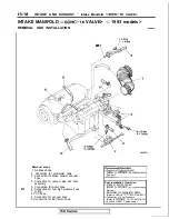
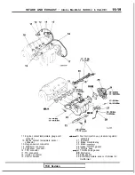
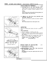
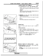
INTAKE AND EXHAUST Service Adjustment Procedures
6 I
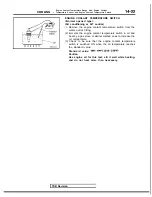
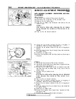
(6) Put a blind plug on the vacuum hose (black) end.
(7) Apply negative pressure when idling. and check the
negative pressure state when the knock sensor is con-
nected and disconnected.
state
Knock sensor
Normal state
connector
I
Idling
NOTE
negative pressure is not normal, it can be assumed that
there is a malfunction in the knock sensor circuit.
(8) Turn off the ignition switch, and connect the connector of
the knock sensor.
(9) Use scan tool to erase the diagnostic trouble code or dis-
connect the
terminal of the battery for 10 seconds or
more.
NOTE
This erases the diagnostic memory of the knock sensor
trouble by disconnecting the knock sensor connector.
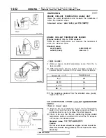
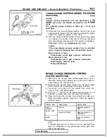
TURBOCHARGER WASTE GATE SOLENOID
INSPECTION
(1) Operation check
Using a hand
pump, apply a negative pressure to
the solenoid valve nipple on which the white vacuum hose
is connected, and check air-tightness when the voltage is
applied to the solenoid valve terminal and when it is released
from the terminal.
I
Other nipple of
Normal state
Opened
Negative pressure
leaks.
I
When applied
Closed by finger
Negative pressure
is maintained.
I
I
I
Negative pressure
is maintained.
I
When released Opened
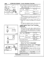
(2) Continuity check of coil
Measure the solenoid valve terminal resistance.
Standard value: 36-44 [at
TURBOCHARGER BYPASS VALVE INSPECTION
(1) Remove the turbocharger bypass valve.
(2) Connect the hand vacuum pump to the nipple of the turbo-
charger bypass valve.
(3) Apply a negative pressure of approx. 53.3
(7.7 psi), and
check operation of the valve. Also check that air tightness
is maintained.
Negative ‘pressure
Valve operation
-1
About 53.3
(7.7 psi)
It starts opening.
I
TSB Revision
Summary of Contents for 1989 Galant
Page 2: ......
Page 4: ...00 z NOTES ...
Page 274: ...13 132 NOTE ...
Page 586: ...NOTES ...
Page 650: ...NOTE ...
Page 664: ...NOTES ...
Page 688: ...NOTES ...
Page 690: ......
Page 692: ......
Page 694: ......
Page 696: ......
Page 698: ......
Page 700: ...c ...
Page 702: ......
Page 704: ......
Page 706: ......
Page 708: ......
Page 710: ......
Page 712: ......
Page 714: ......
Page 716: ......
Page 718: ......
Page 720: ......
Page 722: ......
Page 724: ......
Page 729: ...23 23 NOTES ...
Page 860: ...NOTES ...
Page 921: ...NOTES ...
Page 948: ...33B 9 NOTES ...
Page 1121: ...NOTES ...
Page 1200: ...SERVICE BRAKES Brake Pedal 35 79 Lubrication points Part A 14AO256 1 14UOO5l TSB Revision ...
Page 1273: ...NOTES t ...


