13-8
FUEL SYSTEM
VALVE> Troubleshooting
TROUBLESHOOTING
EXPLANATION OF TROUBLESHOOTING PROCEDURES
Effective troubleshooting procedures related to problems of the
system are described below.
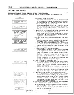
START
1.
of the
2. Read-out of the diag-
nostic trouble code.
I
3. Assumption of the prob-
able cause of the mal-
function, and
of the
appropriate check
4. Checking of the engine
control module’s input
and output signals.
6. Checking of the
component itself.
8. Confirmation that repair
procedures have been
completed and
that
reoccurrence has been
prevented.
Confirmation of the malfunction.
l
Cause the malfunction to reoccur and check the details
of the malfunction and the conditions (engine condition,
driving conditions, etc.) when the malfunction reoccurs.
2.
Read-out of the diagnostic trouble code.
l
When the diagnostic trouble code is read out and the
diagnostic trouble code is output, refer to the diagnos-
tic chart and repair the indicated location of the mal-
function.
3.
Assumption of the probable cause of the malfunction, and
determination of the appropriate check points.
l
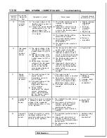
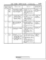
Refer to the “CHECK CHART CLASSIFIED BY PROB-
LEM SYMPTOMS” and confirm the sequence of check-
ing for the indicated malfunction.
4. Checking of the engine control module’s input and output
signals.
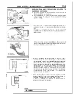
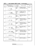
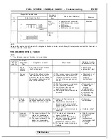
Using the scan tool or an oscilloscope, check the input
and output signals of the engine control module.
If the input and output signals are normal, sensor input/
actuator control can. be judged to be normal, so check
the
input
and output signals of the subsequent check
point.
5.
Checking of the
component’s harness.
l
If an abnormal condition of the input and output signals
of the engine control module is discovered, check, and
repair if necessary, the body harness of the
com-
ponent.
l
After making this repair, again check the input and out-
put signals of the engine control module; if they are
normal, proceed to the checking of the input and out-
put signals of the subsequent check point.
6.
Checking of the
component itself.
If the input and output signals of the engine control
module are abnormal even though the body harness is
normal, check the
component itself, and repair or
replace as necessary.
l
After making this repair or replacement, again check
the input and output signals of the engine control mod-
ule; if they are normal, proceed to the checking of the
input and output signals of the subsequent check point.
7.
Rechecking of the cause of the malfunction, and repair.
l
If the input and output signals of the engine control
module are abnormal even though the harness check-
ing and the checking of the unit itself indicate that the
condition is normal, refer to the troubleshooting hints to
recheck the probable cause, and then check other
groups and reapir as necessary.
8. Confirmation that repair procedures have been completed
and that reoccurrence has been prevented.
l
Perform a test to try to get the malfunction to reoccur,
and confirm that it does not.
Eliminate the true cause of the malfunction so as to
prevent its reoccurrence.
TSB Revision
Summary of Contents for 1989 Galant
Page 2: ......
Page 4: ...00 z NOTES ...
Page 274: ...13 132 NOTE ...
Page 586: ...NOTES ...
Page 650: ...NOTE ...
Page 664: ...NOTES ...
Page 688: ...NOTES ...
Page 690: ......
Page 692: ......
Page 694: ......
Page 696: ......
Page 698: ......
Page 700: ...c ...
Page 702: ......
Page 704: ......
Page 706: ......
Page 708: ......
Page 710: ......
Page 712: ......
Page 714: ......
Page 716: ......
Page 718: ......
Page 720: ......
Page 722: ......
Page 724: ......
Page 729: ...23 23 NOTES ...
Page 860: ...NOTES ...
Page 921: ...NOTES ...
Page 948: ...33B 9 NOTES ...
Page 1121: ...NOTES ...
Page 1200: ...SERVICE BRAKES Brake Pedal 35 79 Lubrication points Part A 14AO256 1 14UOO5l TSB Revision ...
Page 1273: ...NOTES t ...

