


556
34 SAFETY DEVICES, SAFETY LABELS, AND CONSTANTS
34.1 Safety Devices
Safety timer (SA\T)/safety retentive timer (SA\ST)
This device starts measurement when the safety timer coil is turned on. When the current value reaches a setting value, time
is up and the contact is turned on. This safety timer is an up-timing type device and therefore the current value matches a
setting value when the safety timer time is up. Operations other than the following are the same as those for the timer. (
■
Safety timer types
There is a safety timer (SA\T) that retains the current value in 16-bit units. In addition, there is a safety retentive timer (SA\ST)
that retains the current value even if the coil turns off.
■
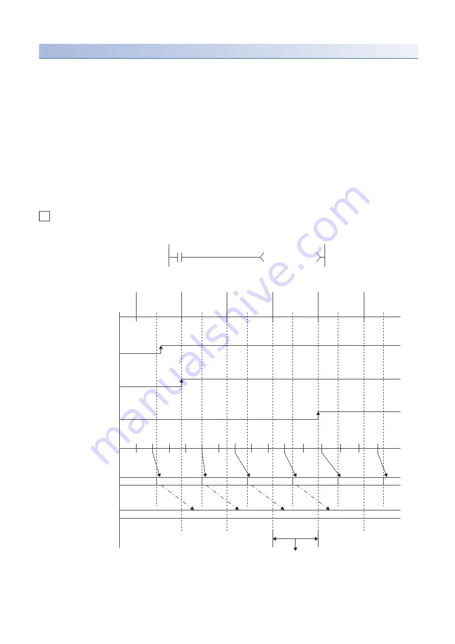
Safety timer accuracy
The current value is measured when starting safety cycle processing. The value for the elapsed time since the previous safety
cycle processing was started until the present is added to the current value when the OUT SA\T
instruction is executed. If
the safety timer coil is off at the execution of the OUT SA\T
instruction, the current value is not updated. The maximum
response accuracy of the timer is the "elapsed time since previous safety cycle processing was started until the p
timer limit setting".
Ex.
Timer limit setting = 10ms, SA\T0 setting value = 8
: Safety cycle processing start
(1) Time accuracy - (Elapsed time since the previous safety cycle processing was started until the p Timer limit setting) to (Elapsed time since the
previous safety cycle processing was started until the present)
(2) Sets the coefficient when starting safety cycle processing.
H
K8
ON
ON
ON
OFF
OFF
OFF
1
2
2
0+2=2
2+3=5
5+2=7
(1)
7+3=10
2
2
1
2
1
2
3
3
3
3
3
3
1
1
1
2
2
2
[Ladder example]
SA\X0
SA\T0
OUT SA\T0
OUT SA\T0
OUT SA\T0
OUT SA\T0
OUT SA\T0
OUT SA\T0
[Current value update timing]
Safety program
SA\X0 of the CPU module
SA\T0 (coil)
SA\T0 (contact)
Measurement (10ms)
(Measured with the timer limit
setting value)
Count when the safety cycle
processing starts
SA\T0 (current value)
Summary of Contents for MELSEC iQ-R-R00CPU
Page 2: ......
Page 151: ...9 MONITOR FUNCTION 9 1 Real Time Monitor Function 149 9 MEMO ...
Page 323: ...18 SEQUENCE SCAN SYNCHRONIZATION SAMPLING FUNCTION 321 18 MEMO ...
Page 330: ...328 20 ROUTING SETTING 20 3 Precautions MEMO ...
Page 423: ...26 BASIC CONCEPT 26 8 State Transition of the Redundant System 421 26 MEMO ...
Page 1014: ...1012 APPX Appendix 15 Added and Enhanced Functions MEMO ...
Page 1027: ......


