[
V
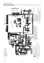
Electrical Wiring Diagram ]
- 56 -
HWE15070
GB
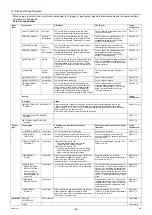
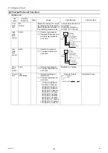
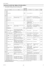
When using a local controller, refer to the table below for the types of input/output signals that are available and the operations that
correspond to the signals.
External Input/Output
Input
type
Dry contact
ON (Close)
OFF (Open)
Terminal
block/connector
(a)UNIT OPERATION
Run/Stop
The unit will go into operation when the water
temperature drops below the preset temperature.
The unit will stop except when the unit is in
the Anti-Freeze mode.
TB6 15-16
(b)MODE CHANGE 2
Heating
Eco/Heating
The unit will go into operation when the water
temperature drops below the temperature setting
for "Water Temp Setting C" (Heating ECO mode)
The unit will go into operation when the
water temperature drops below the
temperature setting for "Water Temp
Setting A." (Heating mode)
CN142A 3-4
(c)PRIORITY MODE
COP/
Capacity
The unit will operate in the energy-efficient mode
(COP priority mode).
The unit will operate at the maximum
capacity setting (Capacity priority mode).
CN142C 2-6
(d)MODE CHANGE 1
Hot
water/Heating
The unit will go into operation when the water
temperature drops below the temperature setting
for "Water Temp Setting B."
The unit will go into operation when the
water temperature drops below the
temperature setting for "Water Temp
Setting A." (Heating mode)
CN142D 1-5
(e)ANTI FREEZE
On/Off
The unit will operate in the Anti-Freeze mode (with
the target temperature between 25-35ºC) when
the contact status of (a) "Unit Operation" is "Stop"
OR the ON/OFF button on the remote controller is
turned off.
The unit will operate according to the status
of the "Unit Operation" contact (item (a)
above) or the ON/OFF command from the
remote controller.
TB6 23-24
(f)FAN MODE
Forced/
Normal
The fan will remain in operation after the
compressor has stopped (including when the
OPERATION status is "STOP").
The fan will stop when the compressor
stops.
TB5 19-20
(g)FLOW SWITCH
Normal/Error
The unit is allowed to operate.
The unit will not operate.
CN142D 2-6
(h)PUMP INTERLOCK
Normal/Error
The unit is allowed to operate.
The unit will not operate.
TB5 11-12
(i)PEAK-DEMAND
CONTROL
On/Off
The unit will operate at or below the maximum
capacity level that was set for the Peak-demand
control setting. (If the maximum capacity setting
for item (c) above "Priority mode" is below the
setting for the Peak-demand control setting, the
unit will operate at whichever capacity is the smaller.)
The unit will operate at or below the
maximum capacity setting for either
"Capacity Priority Mode" or "COP Priority
Mode" that was selected for item (c)
"Priority Mode" above.
CN142C 1-4
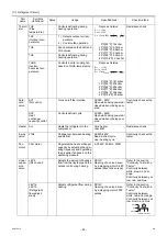
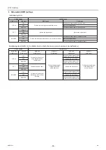
Analog
Terminal
block/connector
Input type
Action
(j)WATER TEMP SETTING/CAPACITY
CONTROL
Water temperature or capacity control can be set by using the external analog input to the
CN421 on the MAIN circuit board. One analog input type can be selected from the following
types: 4-20 mA, 1-5 V, 0-10 V, or 2-10 V. Selection between drain pan output and defrost output
can be made using the item code 1051.
Note: Use a 4-20 mA signal output device with insulation.
CN421 2(+)-3(-)
(k)EXTERNAL WATER SENSOR
(optional)
-
TB6 T1-T2
(l)EXTERNAL WATER SENSOR
(optional)
-
TB6 T3-T4
Output
type
Contact type
Conditions in which the contact closes
(turns on)
Conditions in which the contact opens
(turns off)
Terminal
block/connector
(m)ERROR INDICATOR
Close/Open
The unit has made an abnormal stop.
During normal operation
TB5 74-75
(n)OPERATION
INDICATOR
Close/Open
The "Unit Operation" contact (item (a) above) or
the ON/OFF button on the remote controller is ON.
The "Unit Operation" contact (item (a)
above) or the ON/OFF button on the remote
controller is OFF.
TB5 72-73
(o)PUMP OPERATION
COMMAND
Close/Open
(1)When SW2-8 is set to ON
The pump will operate according to the
Thermo-ON/OFF status of the unit.
(2)When SW2-8 is set to OFF
The pump will operate according to the status
of the "Unit Operation" contact or the ON/OFF
button on the remote controller button.
Under all conditions other than the ones
listed on the left
TB5 70-71
(p)EMERGENCY
SIGNAL
Close/Open
Water temperature has dropped below the Booster
Heater Operation Water Temperature (TWL1
value) (Item code 1057) and the outside
temperature (TAL1 value) (Item code 1058).
Water temperature is at or above
"TWL1+2ºC" or the outside temperature is
at or above "TAL1+2ºC".
MAIN circuit
CN512 1-3
(q)DRAIN PAN
HEATER SIGNAL/
DEFROST SIGNAL
Selects either the
drain pan signal or
defrost signal by Item
code 1056
Close/Open
In case of the defrost signal when item code 1056
is "1", at least one of the circuits is in defrost mode.
In case of the drain pan signal when item
code 1056 is "0", the outside temperature is
above 1ºC or the outside temperature has
risen above 3ºC after the conditions has
been met under which the contact turns on.
In case of the defrost signal when item code
1056 is "1", both circuits are not in defrost
mode.
MAIN circuit
CN512 5-7
(r)DRAIN PAN
HEATER SIGNAL
Close/Open
-
When item code 1056 is "1", the outside
temperature is above 1ºC or the outside
temperature has risen above 3ºC after the
conditions has been met under which the
contact turns on.
SUB circuit
CN512 5-7
(s)EMERGENCY
SIGNAL 2
Close/Open
Water temperature has dropped below the Booster
Heater Operation Water Temperature (TWL2
value) (Item code 1059) or the outside temperature
(TAL2 value) (Item code 1060)
Water temperature is at or above
"TWL2+2ºC" or the outside temperature is
at or above "TAL2+2ºC".
SUB circuit
CN512 1-3
RC/M-NET
REMOTE
CONTROLLER
PAR-W21MAA
TB6 RA-RB
M-NET
-
TB6 MA-MB
0000001906.book 56 ページ 2015年11月5日 木曜日 午前11時55分
Summary of Contents for CAHV-P500YB-HPB
Page 1: ......
Page 7: ...CONTENTS HWE15070 GB ...
Page 9: ... 2 HWE15070 GB ...
Page 19: ... 12 HWE15070 GB ...
Page 37: ... 30 II Restrictions GB HWE15070 ...
Page 39: ... 32 HWE15070 GB ...
Page 48: ... 41 HWE15070 GB IV Remote Controller 1 Using the Remote Controller 43 2 Function Settings 48 ...
Page 49: ... 42 HWE15070 GB ...
Page 57: ... IV Remote Controller 50 HWE15070 GB ...
Page 58: ... 51 HWE15070 GB V Electrical Wiring Diagram 1 Electrical Wiring Diagram 53 ...
Page 59: ... 52 HWE15070 GB ...
Page 65: ... 58 V Electrical Wiring Diagram GB HWE15070 ...
Page 67: ... 60 HWE15070 GB ...
Page 71: ... VI Refrigerant Circuit 64 HWE15070 GB ...
Page 73: ... 66 HWE15070 GB ...
Page 111: ... 104 HWE15070 GB ...
Page 117: ... VIII Test Run Mode 110 HWE15070 GB ...
Page 119: ... 112 HWE15070 GB ...
Page 163: ... IX Troubleshooting 156 HWE15070 GB ...
Page 164: ... 157 HWE15070 GB X Attachments 1 R407C saturation temperature table 159 ...
Page 165: ... 158 HWE15070 GB ...
Page 167: ... X Attachments 160 HWE15070 GB ...
Page 168: ......


