[
VII
Control ]
- 98 -
HWE15070
GB
Cooling/heating Circuit Control and General Function of System Equipment
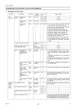
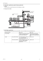
-13- Water-temperature control
Water temperature can be controlled in the following three ways. Select one that works best.
*1 When dip switch SW2-8 is set to ON, the ON/OFF operation of the units is controlled based on the external water
temperature sensor reading.
How the operating frequency of the compressor is controlled depends on the SW3-3 setting (outlet-/inlet-based control
option).
(Sub units will be controlled based on the water-temperature control method that has been selected for the Main unit.)
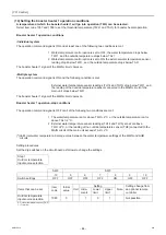
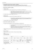
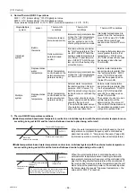
1. When the units are restarted after stopping for under a condition other than Thermo-OFF
Conditions for the units to stop other than the Thermo-OFF condition
The control option was changed from built-in thermistor reading based control to the external thermistor reading based
control.
Pump interlock is off.
When one of the units in a set is forced to stop
When the Capacity priority/Cop priority setting was changed.
When the units were stopped under the following conditions:
1. Tmax has reached 65ºC (when the outside temperature
≤
-10ºC) or
2. Tmax has reached 70ºC (when the outside temperature > -10ºC.
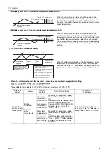
DIFF1 = 2 ºC (Initial setting): “1015” Digitally set value
DIFF2 = 2 ºC (Initial setting): “1016” Digitally set value
Tmax (Outside temperature
≤
-10 ºC: 65ºC, Outside temperature > -10 ºC : 70ºC)
Switch Factory
setting
Outlet-water-temperature-based control
SW3-3
OFF
Inlet-water-temperature-based control
-
Water temperature control based on the
external water temperature reading
SW2-8
OFF
SW3-3
SW2-8
Outlet-water-temperature-based control
OFF
OFF
Inlet-water-temperature-based control
ON
OFF
Water temperature control based on the
external water temperature reading
Arbitrary
*1
ON
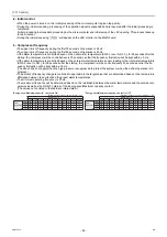
Single/Multiple system
sensor
Control method
Thermo-ON conditions
Individual system
Built-in thermistor
Inlet-water-tempera-
ture-based control
Outlet water temperatures
< (Preset water temperature - DIFF1ºC)
AND
Inlet water temperatures
< (Preset water temperature - DIFF1ºC)
Outlet-water-temper-
ature-based control
Outlet water temperatures
< (Preset water temperature - DIFF1ºC)
AND
Inlet water temperatures
< (Preset water temperature - DIFF1ºC)
AND
Average outlet water temperature
≤
(Preset water temp DIFF2ºC)
Representative water
temperature
Representative water
temperature
Representative water temperature
< (Preset water temperature - DIFF1ºC)
Multiple system
Representative water
temperature
Representative water
temperature
Representative water temperature
< (Preset water temperature - DIFF2/2)
AND
The number of units to run an optimal opera-
tion will be determined by the main unit.
(The unit with the least amount of cumulative
operation hours will go into operation first.)
0000001906.book 98 ページ 2015年11月5日 木曜日 午前11時55分
Summary of Contents for CAHV-P500YB-HPB
Page 1: ......
Page 7: ...CONTENTS HWE15070 GB ...
Page 9: ... 2 HWE15070 GB ...
Page 19: ... 12 HWE15070 GB ...
Page 37: ... 30 II Restrictions GB HWE15070 ...
Page 39: ... 32 HWE15070 GB ...
Page 48: ... 41 HWE15070 GB IV Remote Controller 1 Using the Remote Controller 43 2 Function Settings 48 ...
Page 49: ... 42 HWE15070 GB ...
Page 57: ... IV Remote Controller 50 HWE15070 GB ...
Page 58: ... 51 HWE15070 GB V Electrical Wiring Diagram 1 Electrical Wiring Diagram 53 ...
Page 59: ... 52 HWE15070 GB ...
Page 65: ... 58 V Electrical Wiring Diagram GB HWE15070 ...
Page 67: ... 60 HWE15070 GB ...
Page 71: ... VI Refrigerant Circuit 64 HWE15070 GB ...
Page 73: ... 66 HWE15070 GB ...
Page 111: ... 104 HWE15070 GB ...
Page 117: ... VIII Test Run Mode 110 HWE15070 GB ...
Page 119: ... 112 HWE15070 GB ...
Page 163: ... IX Troubleshooting 156 HWE15070 GB ...
Page 164: ... 157 HWE15070 GB X Attachments 1 R407C saturation temperature table 159 ...
Page 165: ... 158 HWE15070 GB ...
Page 167: ... X Attachments 160 HWE15070 GB ...
Page 168: ......

