[
II
Restrictions ]
- 20 -
HWE15070
GB
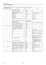
(2) Table of settings items
Set the dip switches SW2 and SW3 as shown in the table below to set the value for the items in the "Setting item" column.
SW2 and SW3 settings
Setting Item
Item
Code
Default
Notes
SW2-1 SW3-8 SW3-9 SW3-10
OFF
OFF
ON
OFF
Maximum peak-demand capacity
2 100%
Peak-demand control start time
3 13:00
Peak-demand control end time
4 13:00
Remote water temperature input signal type
21 0
0: 4-20 mA; 1: 0-10V; 2: 0-5 V; 3: 2-10V
Setting temp D,E
for analog input
11
13
D=45ºC, E=65ºC
When SW2-7 is set to ON
Setting temp A
(Heating mode)
11 45ºC
Range 25-70
Setting temp B
(Hot water mode)
13 65ºC
Range 25-70
Heating ECO mode/2-point system or Curve
20 1
0: 2-point system
1: Curve
Setting temp C1,C2,C3,C4,C5,C6 for Setting temp
C for Heating ECO mode
22-25
C1=60ºC; C2=0ºC
C3=35ºC; C4=25ºC
C5=47.5ºC; C6=12.5ºC
Enable/disable schedule setting
5 0
Set to "1" to enable scheduled operation.
ON-time 1 (schedule mode without remote)
6 0:00
OFF-time 1 (schedule mode without remote)
7 0:00
ON-time 2 (schedule mode without remote)
8 0:00
OFF-time 2 (schedule mode without remote)
9 0:00
ON-time 3 (schedule mode without remote)
18 0:00
OFF-time 3 (schedule mode without remote)
19 0:00
Current time
1
Set the current time.
TWL1
1057 40
Water temperature 1 for emergency signal
1
TAL1
1058 -10
Outside temperature 1 for emergency
signal 1
TWL2
1059 30
Water temperature 2 for emergency signal
2
TAL2
1060 -15
Outside temperature 2 for emergency
signal 2
Drain pan heater/Defrost signal
1056 0
Selects between drain pan output and
defrost output for MAIN circuit board
(CN512 5-7) output.
Water temperature/Capacity control
1051 0
0: Water temperature input 4-20 mA
1: Capacity control input 4-20 mA
2: Water temperature input IT terminal
3: Capacity control input IT terminal
OFF
ON
OFF
OFF
Setting temp selection 1 (ON-time 1-OFF-time 1)
1218 A (1)
A=1; B=2; C=3
Setting temp selection 2 (ON-time 2-OFF-time 2)
1219 A (1)
A=1; B=2; C=3
Setting temp selection 3 (ON-time 3-OFF-time 3)
1220 A (1)
A=1; B=2; C=3
Control Sensor selection (Target Setting temp A)
1215 TH14
Selectable from TH14 or TH15
Control Sensor selection (Target Setting temp B)
1216 TH14
Selectable from TH14 or TH15
Control Sensor selection (Target Setting temp C)
1217 TH14
Selectable from TH14 or TH15
Thermo differential 2
1016 2.0
Range 0-8
Multiple System Thermo-ON/OFF prohibition
periods
1020 1
Range 1-5
Outdoor temperature input source selection
1080 0
0: Outdoor temperature sensor (TH9)
1: IT terminal
0000001906.book 20 ページ 2015年11月5日 木曜日 午前11時55分
Summary of Contents for CAHV-P500YB-HPB
Page 1: ......
Page 7: ...CONTENTS HWE15070 GB ...
Page 9: ... 2 HWE15070 GB ...
Page 19: ... 12 HWE15070 GB ...
Page 37: ... 30 II Restrictions GB HWE15070 ...
Page 39: ... 32 HWE15070 GB ...
Page 48: ... 41 HWE15070 GB IV Remote Controller 1 Using the Remote Controller 43 2 Function Settings 48 ...
Page 49: ... 42 HWE15070 GB ...
Page 57: ... IV Remote Controller 50 HWE15070 GB ...
Page 58: ... 51 HWE15070 GB V Electrical Wiring Diagram 1 Electrical Wiring Diagram 53 ...
Page 59: ... 52 HWE15070 GB ...
Page 65: ... 58 V Electrical Wiring Diagram GB HWE15070 ...
Page 67: ... 60 HWE15070 GB ...
Page 71: ... VI Refrigerant Circuit 64 HWE15070 GB ...
Page 73: ... 66 HWE15070 GB ...
Page 111: ... 104 HWE15070 GB ...
Page 117: ... VIII Test Run Mode 110 HWE15070 GB ...
Page 119: ... 112 HWE15070 GB ...
Page 163: ... IX Troubleshooting 156 HWE15070 GB ...
Page 164: ... 157 HWE15070 GB X Attachments 1 R407C saturation temperature table 159 ...
Page 165: ... 158 HWE15070 GB ...
Page 167: ... X Attachments 160 HWE15070 GB ...
Page 168: ......


