[
V
Electrical Wiring Diagram ]
- 53 -
HWE15070
GB
V
Electrical Wiring Diagram
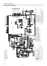
[1] Electrical Wiring Diagram
5
4
6
2 1
3
5 4
6
3
1
2
34
L3
L3
L2
L2
L1
L1
N
N
5
61
32
42
22
12
3
13
26
46
4
55
4
3
3
2
2
1
1
1
1
13
11
1
23
2
24
22
2
12
3
11
1
66
6
77
7
55
5
44
4
33
3
22
2
2
2
2
2
1
1
1
1
1
11
3
33
4
2 1
3
4
1
1
1
1
2
2
2
3
3
3
3456
1
1
1
2
2
2
2
2
3
7
6
5
4
1
2
2
1
1
4
4
4
4
2
2
2
2
5
5
5
4
4
4
3
3
3
2
2
2
2
1
1
1
3
1
1
1
1
3
3
4
1
6
6
6
7
7
3
2
2
2
2
1
1
1
1
3
3
3
3
2
2
1
1
3
3
2 1
3
LED4: Power supply
SW421
2
1
ON
OFF
Flow switch
Mode change 1
Capacity mode
Demand
Anti freeze
23
24
T3
T4
TH15
CN406 yellow
(Hot water/
Heating)
(Normal/Error)
(ON/OFF)
(ON/OFF)
(ON/OFF)
(ON/OFF)
(COP
priority/
Capacity
priority)
Pump
interlock
(Normal/Error)
Fan mode
(coercion/
by ordinary)
Run
Run/Stop
Mode
change 2
(Heating Eco/
Heating)
No-V
oltage
contact
input
SW01
SW02
SW03
ON
OFF
ON
OFF
ON
OFF
CN332
blue
MAIN BOX
LED1
Control Board
LED3: Remote controller
lit while energized
LED2: CPU in operation
Unit address setting
(0)
10'
digit
SWU1
(1)
1'
digit
(0)
SWU2
SWU3
2
1
1
2
3
4
5
6
7
8
9
10
1
2
10
10
9
8
7
6
5
4
3
3
4
5
6
7
8
9
ENTER
SWP2
SWP3
UP
SWP1
DOWN
B
A
OFF
LOCAL
SWS1
SWS2
REMOTE
63H1
X07
X06
X05
X09
X04
X08
X01
X02
X03
CN502
CN501
CH
SV1
SV2
21S4
72C
CNAC
red
black
CNAC2
CN421 black
DC12V
No-voltage contact output
Pump operation
command output
Emergency
signal A
(for extra
heater)
*11
Drain pan
heater/
Defrost signal
Error display output
Operation display
output
pump error
T1
(+)
(–
)
T2
12
11
20
19
16
RB
MB
B
MA
A
RA
15
74
75
71
70
72
66
62
73
63LS
63HS
TH9
TH4
TH1
TH14
TH16
TH1
1
CN408
TH2
M
TH3
LEV1
52P
51P
CNL
VC
blue
M
LEV2
CNL
V
A
CN407 red
CN3A
blue
blue
CN51
1
yellow
CN512
CN4
CN2
Contorol
power circuit
CN510
CN142A
black
Outdoor temp. 1
Air hex Ref
temp. 1
*12, *13
Wa
ter temp. setting
Analog input
4~20mA/0~10V
1~5V/2~10V
Capacity
control signal
Discharge Ref
temp. 1
Suction Ref
temp. 1
Wa
ter inlet
temp. 1
External
Wa
ter sensor. 1
External
Wa
ter sensor. 2
Wa
ter outlet
temp. 1
Shell Ref temp. 1
Optional remote controller
connecting terminal
(Non-polarized)
T
ransmission cable for multiple unit control
Measurement terminal for maintenance (M-NET)
T
O
SUB BOX
TB3
T
o
SUB BOX
TB4
F06 AC250V 3.15A
T
F2
L1
L2
L3
N
CN63LS red
CN405 blue
CN402 green
CN404 black
CN401
CN142B
blue
CN142C
CN142D
blue
CN801
yellow
CN102
Z21
52P
PL
M
3~
MP
CN63HS
TB2
ELB1
ELB2
TB1
L1
L2
L3
N
CNTYP1 black
power supply
3N~
50Hz
380/400/415V
power supply
3N~
50Hz
380/400/415V
C5
Z5
C3
C2
F02
R01
R02
F01
R03
Z1
Z2
R34
C30
C32
C34
C36
black
F03
F04 AC250V 6.3A
T
black
white
L
F01,F02,F03 AC250V 6.3A
T
DSA
R35
CT3
white
R33
SC-L3
R30
red
red
white
white
D1
R04
R32
R06
CN2
C31
CN18V blue
U
Z4
C17
CN4 red
TB21
CN1B
L1
CN1A
red
Noise
Filter
TB22
CN3 green
TB24
Fan motor
(Heat exchanger)
W
a
ter side
Heat exchanger
N
C33
TB23
IPM
F
A
N Board
F05 AC/DC400V 10A
T
*2
M
3~
MS
3~
black
U
red
Diode
Bridge
2
72C
1
black
SC-P2
C7
C8
CT12
L2
R5
U
LED1: Normal
operation
+
red
C35
DCL
SC-L2
SC-P1
SC-U
CN1
black
black
C37
CN5V yellow
C1
C9
C10
CN6
4
C100
LED1: Normal operation (lit)
/ Error (blink)
Motor
(Compressor)
LED3: CPU in
operation
R1
CN4
CN2
SC-V
U
IGBT
CT22
U
CNINV
SC-W
SC-L1
W
CN21 blue
U
U
V
W
CNVDC
CN4 blue
C631
t°
LED2: Error
R630
R631
CN22 red
Z3
CN5
R31
C6
CNTYP
black
CNTYP2
CN52C red
TB5
TB5
TB6
TB6
TB6
TB6
TB5
TB6
TB6
CNDC Pink
C1
RSH1
THHS
FT
-P
P
N
FT
-N
C4
+
INV Board
+
C630
+
+
+
+
+
+
3
red
L3
THBOX
–
+
V
t°
t°
t°
t°
t°
t°
t°
t°
t°
t°
black
5 4
3
1
2
CN105
IT
TERMINAL
Note
3.
The symbols
used for dif
fere
nt types of term
inals are as follows
:
: T
erminal blo
c
k
: Cut the sho
rt-circuit wire, and co
nnect field wiring
: Bullet termina
l (field supply: male
ø3.96)
Note
4.
T
o
switch be
tween "Ca
p
acity prio
rity" and "
COP priority
,"
remove the
short-circuit wire
on terminal 23 a
nd CN142-6.
Note
5.
The broke
n
lines indicate th
e optional p
a
rt
s, field-supplied p
a
rt
s, and
field work.
Note
6.
Be sure to
connect the w
ire
s from terminals 1
1
and 12 to th
e interlock
cont
act on the p
ump.
A short-circuit
may cause abn
ormal stop or malfu
nctions.
Note
7.
Operation signa
ls can be re
ceived from th
e remote cont
roller or through
the dry cont
act. The tem
perature setting
can be chang
ed by a signal
received through
the dry cont
act or by u
sing the schedu
le setting.
Note 8.
Leave a sp
ace of at le
ast 5 cm betwee
n the low volt
age extern
al wiring
(no-volt
a
g
e
cont
act inpu
t and
re
mote contro
ller wiring) a
nd wiring
of 100
V or greater
. Do
not place them
in the same con
duit tube or cab
tyre
cable as this will da
mage the circuit
board.
Note 9.
The volt
a
ge/current app
lied to the dry co
nt
act sh
ould not excee
d
12
VDC/5 mA.
No
te 10.
When
cabtyre cable is u
sed for the con
trol cable wiring, u
se a sep
arate
cabtyre
cable for the f
ollowing wiring.
Using t
he same cabtyre
cable may cause
malfunctions an
d damage to
the u
nit.
(a)
Option
al remote controlle
r wiring
(b)
No-volt
age con
tact inpu
t wiring
(c)
No-volt
age con
tact out
put wiring
(d)
Remote
water temp. sett
ing
No
te 1
1
.
Select
s
either D
rain p
a
n
signal or Defrost s
ignal by SW2 an
d SW3
setting
s. (Item code 10
56)
No
te
12.
Select
s
either W
ater tempe
rature setting input signa
l
or Cap
acity control
input
signal by SW2 an
d SW3 settings.
(Item code 1051
)
No
te 13.
Use a
4-20 mA signal ou
tput device with
insulation.
Feedin
g
30 mA or more
current may dama
ge the circuit bo
ard.
Not
e1.
S
ingl
e-dot
te
d line
s
ind
ica
te
f
ield
wiri
ng.
Note2.
Fa
ston
termina
ls ha
ve
a
locking
function.
Check that
the
termin
a
ls a
re
securely
locked
in place af
ter
in
se
rtio
n.
Pre
ss
the t
a
b
in th
e
mid
d
le of th
e
termin
a
ls
to
remove them.
0000001906.book 53 ページ 2015年11月5日 木曜日 午前11時55分
Summary of Contents for CAHV-P500YB-HPB
Page 1: ......
Page 7: ...CONTENTS HWE15070 GB ...
Page 9: ... 2 HWE15070 GB ...
Page 19: ... 12 HWE15070 GB ...
Page 37: ... 30 II Restrictions GB HWE15070 ...
Page 39: ... 32 HWE15070 GB ...
Page 48: ... 41 HWE15070 GB IV Remote Controller 1 Using the Remote Controller 43 2 Function Settings 48 ...
Page 49: ... 42 HWE15070 GB ...
Page 57: ... IV Remote Controller 50 HWE15070 GB ...
Page 58: ... 51 HWE15070 GB V Electrical Wiring Diagram 1 Electrical Wiring Diagram 53 ...
Page 59: ... 52 HWE15070 GB ...
Page 65: ... 58 V Electrical Wiring Diagram GB HWE15070 ...
Page 67: ... 60 HWE15070 GB ...
Page 71: ... VI Refrigerant Circuit 64 HWE15070 GB ...
Page 73: ... 66 HWE15070 GB ...
Page 111: ... 104 HWE15070 GB ...
Page 117: ... VIII Test Run Mode 110 HWE15070 GB ...
Page 119: ... 112 HWE15070 GB ...
Page 163: ... IX Troubleshooting 156 HWE15070 GB ...
Page 164: ... 157 HWE15070 GB X Attachments 1 R407C saturation temperature table 159 ...
Page 165: ... 158 HWE15070 GB ...
Page 167: ... X Attachments 160 HWE15070 GB ...
Page 168: ......

