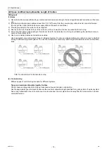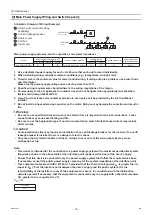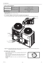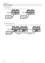
[
II
Restrictions ]
- 22 -
HWE15070
GB
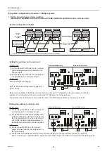
(4) System configuration procedures : Multiple system
1. Set the dip switches and rotary switches.
(Switches on the MAIN circuit on the main unit* AND the MAIN and SUB circuits on all sub units)
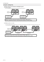
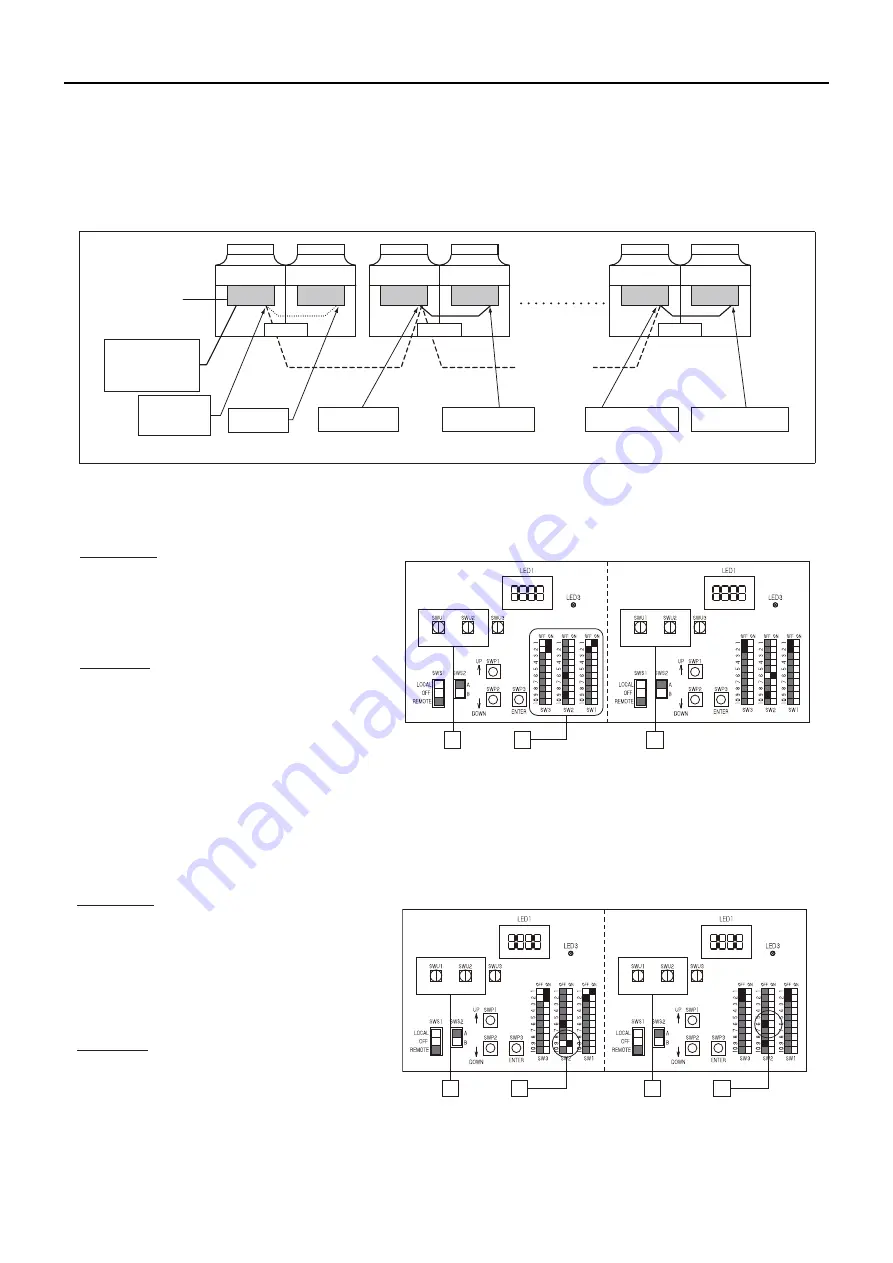
System configuration diagram
Setting the switches on the main unit
MAIN circuit
(1) Set the dip switch SW2-8 to ON. (an external
water temperature sensor) (labeled A in the
figure at right)
(2) Set the dip switch SW2-9 to ON. (multiple unit
control)(labeled A in the figure at right)
SUB circuit
Nothing needs to be changed.
Refer to "Dip switch settings table" (page 67) for
further details.
Make sure the address of the MAIN circuit on the main unit is set to "1" (labeled B in the figure above) and that the
address of the SUB circuit on the main unit is set to "51" (labeled C in the figure above).
The address of each SUB circuit should equal the sum of the MAIN circuit address on the same unit and 50.
External
water
temperature
sensor
SW2-8: ON
SW2-9: ON
Address: 1
Address: 51
SW2-9: ON
Address: 2
SW2-9: ON
Address: 1 + n
SW2-6: OFF
Address: 52
SW2-6: OFF
Address: 50 + n
Inter-unit wiring
(M-NET line)
* The main unit is the unit to which an external water temperature sensor is connected.
Main
unit
Sub unit
"n"th unit
Unit (MAIN circuit)
PCB
Unit (SUB circuit)
PCB
Unit (MAIN circuit)
PCB
Unit (SUB circuit)
PCB
Sub unit
Unit (MAIN circuit)
PCB
Unit (SUB circuit)
PCB
A
B
C
Main unit (SUB circuit)
Main unit (MAIN circuit)
10’s digit (0) 1’s digit (1)
(0)
10’s digit (5) 1’s digit (1)
(0)
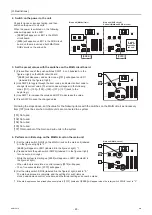
Setting the switches on all sub units
MAIN circuit
(1) Set the dip switch SW2-9 to ON. (multiple unit
control) (labeled A in the figure at right)
(2) Set the MAIN circuit addresses with the rotary
switches. (labeled B in the figure at right). Set
the 10's digit with SWU1, and set the 1's digit
with SWU2. Assign sequential addresses to
the MAIN circuit on all sub units starting with 2.
SUB circuit
(3) Set the dip switch SW2-6 to OFF. (power
supply to communication circuit) (labeled C in
the figure at right)
(4) Set the SUB circuit addresses with the rotary switches (labeled D in the figure above). Set the 10's digit with
SWU1, and set the 1's digit with SWU2. Assign sequential addresses to the SUB circuit on all sub units starting with 52.
A
B
D
C
Sub unit (MAIN circuit)
Sub unit (SUB circuit)
10’s digit (0) 1’s digit (1)
(0)
10’s digit (5) 1’s digit (1)
(0)
Field-supplied dry
contact switch/relay
or remote controller
(PAR-W21MAA)
0000001906.book 22 ページ 2015年11月5日 木曜日 午前11時55分
Summary of Contents for CAHV-P500YB-HPB
Page 1: ......
Page 7: ...CONTENTS HWE15070 GB ...
Page 9: ... 2 HWE15070 GB ...
Page 19: ... 12 HWE15070 GB ...
Page 37: ... 30 II Restrictions GB HWE15070 ...
Page 39: ... 32 HWE15070 GB ...
Page 48: ... 41 HWE15070 GB IV Remote Controller 1 Using the Remote Controller 43 2 Function Settings 48 ...
Page 49: ... 42 HWE15070 GB ...
Page 57: ... IV Remote Controller 50 HWE15070 GB ...
Page 58: ... 51 HWE15070 GB V Electrical Wiring Diagram 1 Electrical Wiring Diagram 53 ...
Page 59: ... 52 HWE15070 GB ...
Page 65: ... 58 V Electrical Wiring Diagram GB HWE15070 ...
Page 67: ... 60 HWE15070 GB ...
Page 71: ... VI Refrigerant Circuit 64 HWE15070 GB ...
Page 73: ... 66 HWE15070 GB ...
Page 111: ... 104 HWE15070 GB ...
Page 117: ... VIII Test Run Mode 110 HWE15070 GB ...
Page 119: ... 112 HWE15070 GB ...
Page 163: ... IX Troubleshooting 156 HWE15070 GB ...
Page 164: ... 157 HWE15070 GB X Attachments 1 R407C saturation temperature table 159 ...
Page 165: ... 158 HWE15070 GB ...
Page 167: ... X Attachments 160 HWE15070 GB ...
Page 168: ......

