[
II
Restrictions ]
- 18 -
HWE15070
GB
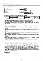
[5] Switch Types and the Factory Settings
1
2
3
4
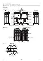
(1) Switch names and functions
There are four main ways to set the settings as follows:
Dip switches (SW1 - SW3)
Dip switches used in combination with the push switches
Rotary switches
Slide switches
See below for how these switches are used to set certain items.
(2)
Different types of switches on the PCB
Initial Setting
MAIN circuit
SUB circuit
"
5
"
"
0
"
.
)
m
e
t
s
y
s
e
l
p
i
t
l
u
M
(
s
s
e
r
d
d
a
t
i
n
u
e
h
t
f
o
t
i
g
i
d
s
'
0
1
e
h
t
s
t
e
S
)
1
U
W
S
(
h
c
t
i
w
s
y
r
a
t
o
R
"
1
"
"
1
"
.
)
m
e
t
s
y
s
e
l
p
i
t
l
u
M
(
s
s
e
r
d
d
a
t
i
n
u
e
h
t
f
o
t
i
g
i
d
s
'
1
e
h
t
s
t
e
S
)
2
U
W
S
(
h
c
t
i
w
s
y
r
a
t
o
R
"
0
"
"
0
"
.
)
F
o
t
t
e
s
n
e
h
w
(
m
e
t
s
y
s
e
h
t
s
t
e
s
e
r
r
o
p
u
s
t
r
a
t
S
)
3
U
W
S
(
h
c
t
i
w
s
y
r
a
t
o
R
Slide switch (SWS1)
LOCAL
OFF
REMOTE
The action that the switch takes when set to a certain position depends
on the type of system configuration (e.g., individual or multiple system)
REMOTE
REMOTE
Slide switch (SWS2)
Unused
A
A
Push switch (SWP1)
Switches the display between the item code and the current value for a specific item.
Increases value.
-
-
Push switch (SWP2)
Switches the display between the item code and the current value for a specific item.
Decreases value.
-
-
Push switch (SWP3)
Advances the item code.
Saves the changed value.
-
-
Dip switches (SW1-3) Switches the LED display contents.
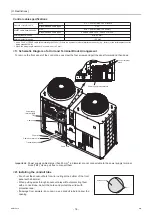
Control box
(Main circuit)
Service panel
Water outlet
Water inlet
Control box
(Sub circuit)
Discharge air outlet
Intake air inlet
Service panel
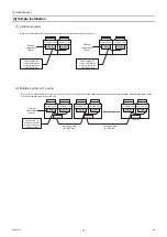
Rotary switch (SWU3) (0-F)
Rotary switch (SWU2) (0-9)
Rotary switch (SWU1) (0-9)
Slide switch (SWS1)
(LOCAL, OFF, and REMOTE
from the top)
Push switch (SWP1) "UP"
Push switch (SWP2) "DOWN"
Push switch (SWP3) "ENTER"
Slide switch (SWS2)
(A and B from the top)
Switches
]
s
e
h
c
t
i
w
s
e
h
t
f
o
w
e
i
v
d
e
g
r
a
l
n
E
[
]
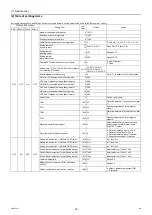
Entire view of a PCB
[
LED display
Dip switch (SW1)
Dip switch (SW2)
Dip switch (SW3)
Slide the dip
switches; do not
push down the
switches.
0000001906.book 18 ページ 2015年11月5日 木曜日 午前11時55分
Summary of Contents for CAHV-P500YB-HPB
Page 1: ......
Page 7: ...CONTENTS HWE15070 GB ...
Page 9: ... 2 HWE15070 GB ...
Page 19: ... 12 HWE15070 GB ...
Page 37: ... 30 II Restrictions GB HWE15070 ...
Page 39: ... 32 HWE15070 GB ...
Page 48: ... 41 HWE15070 GB IV Remote Controller 1 Using the Remote Controller 43 2 Function Settings 48 ...
Page 49: ... 42 HWE15070 GB ...
Page 57: ... IV Remote Controller 50 HWE15070 GB ...
Page 58: ... 51 HWE15070 GB V Electrical Wiring Diagram 1 Electrical Wiring Diagram 53 ...
Page 59: ... 52 HWE15070 GB ...
Page 65: ... 58 V Electrical Wiring Diagram GB HWE15070 ...
Page 67: ... 60 HWE15070 GB ...
Page 71: ... VI Refrigerant Circuit 64 HWE15070 GB ...
Page 73: ... 66 HWE15070 GB ...
Page 111: ... 104 HWE15070 GB ...
Page 117: ... VIII Test Run Mode 110 HWE15070 GB ...
Page 119: ... 112 HWE15070 GB ...
Page 163: ... IX Troubleshooting 156 HWE15070 GB ...
Page 164: ... 157 HWE15070 GB X Attachments 1 R407C saturation temperature table 159 ...
Page 165: ... 158 HWE15070 GB ...
Page 167: ... X Attachments 160 HWE15070 GB ...
Page 168: ......

