[
V
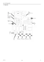
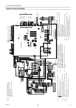
Electrical Wiring Diagram ]
- 54 -
HWE15070
GB
41
2
3
5
6
7
2
1
2
1
2 1
5
4
1
1
2
3
4
2
5
2
12
3
2
3
3
4
4
2
1
6
1
3
2
1
2
1
7
2
3
1
3
6
1
2
5
6
1
2
3
4
1
2
4
1
3
4
5
6
12
3
4
1
13
2
1
2
3
12
2
1
3
2
7
5
3
1
1
2
23
7
3
6
1
4
2
3
1
2
2
1
2
3
4
5
76
1
1
2
3
1
2
21
1
2
3
4
5
6
2
2 1
3
2
5
4
4
3
2
1
1
2
2 1
3
3
2
13
2
1
2
21
1
12
34
34
5
2
2
4
3
3
1
1
1
5
4
1
3
2
13
26
46
5
4
3
2
1
L1
L1
L2
L2
L3
L3
N
N
1
3
OFF
O
N
1
2
SW421
LED4: Power supply
Drain pan
heater
Emergency
signal B
(for extra
heater)
X08
X09
yellow
CN512
Control Board
Z21
CN404 black
TH8
Air hex Ref
temp. 2
72C
Wa
ter inlet
temp. 2
Discharge Ref
temp. 2
Shell Ref temp. 2
Suction Ref
temp. 2
Wa
ter outlet
temp. 2
CN2
CN4CN332
blue
SUB BOX
blue
CN51
1
CNDC Pink
SV2
F06
AC250V
3.15A
T
X07
CNAC
red
Contorol
power
circuit
CNTYP1 black
black
CNAC2
(1)
1'
digit
(5)
10'
digit
Unit adrress setting
(0)
LED2: CPU in operation
LEV2
LEV1
X03
63H1
CN801
yellow
DOWN
UP
ENTER
SWP1
SWP2
SWP3
B
A
OFF
LOCAL
SWU3
SWU1
SWU2
10
10
9
8
7
6
5
4
3
2
1
ON
ON
ON
OFF
OFF
OFF
SW03
SW02
SW01
1
2
3
4
5
6
7
8
9
10
1
2
3
4
5
6
7
8
9
SWS1
SWS2
REMOTE
LED1
LED3: Lit while
energized
TH13
TH12
TH5
TH6
TH7
63LS
63HS
CN63HS
CN63LS red
CN401
CN407 red
CN402 green
CNS2
yellow
CN102
CN102
CNIT
red
B
S
TP2
A
A/M1B/M2
TB3
TP1
T
ransmission
power board
CN04
red
Transmission
power
circuit
TB7
LED1: Power feeding
X01
X02
CN502
CN501
CH
SV1
21S4
M
CNL
VC
blue
M
CNL
V
A
T
o
MAIN BOX
MA
*2
MB
T
o
MAIN BOX
TB2
CNS2
yellow
CNIT
red
TB4
CN52C red
C5
Z5
C3
C2
F02
R01
R02
F01
R03
Z1
Z2
R34
C30
C32
C34
C36
black
F03
F04
AC250V
6.3A
T
black
white
L
F01,F02,F03
AC250V
6.3A
T
DSA
R35
CT3
R05
white
R33
SC-L3
R30
red
white
D1
R04
R32
R06
CN2
C31
CN18V blue
U
Z4
CN5 red
C17
CN4 red
TB21
CN1B
L1
CN1A
red
Noise
Filter
TB22
CN3 green
TB24
Fan motor
(Heat exchanger)
Motor
(Compressor)
N
C33
TB23
IPM
F
A
N Board
F05 AC/DC400V 10A
T
M
3~
MS
3~
black
U
red
Diode Bridge
2
72C
1
black
SC-P2
C7
C8
CT12
L2
R5
U
LED1: Normal
operation
+
red
C35
DCL
SC-L2
SC-P1
SC-U
CN1
black
C37
CN5V yellow
C1
C9
C10
CN6
4
C100
LED1: Normal operation (lit)
/ Error (blink)
LED3: CPU in
operation
R1
CN4
CN2
SC-V
U
IGBT
CT22
U
CNINV
SC-W
SC-L1
W
W
black
white
red
CN21 blue
U
U
CNVDC
CN4 blue
C631
LED2: Error
R630
R631
CN22 red
Z3
CN5
R31
C6
CNTYP
black
C1
RSH1
THHS
FT
-P
P
N
FT
-N
C4
+
INV Board
+
C630
+
+
+
+
+
+
3
red
L3
THBOX
–
+
V
V
CNTYP2
t°
t°
t°
t°
t°
t°
t°
t°
black
W
a
ter side
Heat exchanger
Note 1
.
Si
ngle-
dotte
d l
ines
indicate
fi
eld
wiring
.
Note
2
.
Faston te
rminals have a locking functi
on.
Che
c
k th
at the te
rminal
s
ar
e secur
ely l
o
cke
d
i
n
p
lace
af
ter
insertion
.
Pr
ess the t
a
b in the middle
o
f th
e ter
m
inals to
re
move
the
m
.
0000001906.book 54 ページ 2015年11月5日 木曜日 午前11時55分
Summary of Contents for CAHV-P500YB-HPB
Page 1: ......
Page 7: ...CONTENTS HWE15070 GB ...
Page 9: ... 2 HWE15070 GB ...
Page 19: ... 12 HWE15070 GB ...
Page 37: ... 30 II Restrictions GB HWE15070 ...
Page 39: ... 32 HWE15070 GB ...
Page 48: ... 41 HWE15070 GB IV Remote Controller 1 Using the Remote Controller 43 2 Function Settings 48 ...
Page 49: ... 42 HWE15070 GB ...
Page 57: ... IV Remote Controller 50 HWE15070 GB ...
Page 58: ... 51 HWE15070 GB V Electrical Wiring Diagram 1 Electrical Wiring Diagram 53 ...
Page 59: ... 52 HWE15070 GB ...
Page 65: ... 58 V Electrical Wiring Diagram GB HWE15070 ...
Page 67: ... 60 HWE15070 GB ...
Page 71: ... VI Refrigerant Circuit 64 HWE15070 GB ...
Page 73: ... 66 HWE15070 GB ...
Page 111: ... 104 HWE15070 GB ...
Page 117: ... VIII Test Run Mode 110 HWE15070 GB ...
Page 119: ... 112 HWE15070 GB ...
Page 163: ... IX Troubleshooting 156 HWE15070 GB ...
Page 164: ... 157 HWE15070 GB X Attachments 1 R407C saturation temperature table 159 ...
Page 165: ... 158 HWE15070 GB ...
Page 167: ... X Attachments 160 HWE15070 GB ...
Page 168: ......

