[
VII
Control ]
- 90 -
HWE15070
GB
Control at Start-up
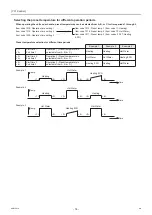
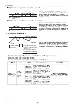
-4- Defrost operation
1. Defrost
start
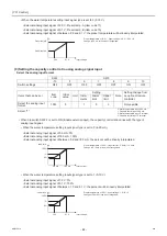
The defrost cycle will start when one of the following conditions 1 through 3 is met.
Defrost operation will be performed individually in the circuit that meets the defrost-start condition below. Defrost operations
will not be performed simultaneously in multiple circuits.
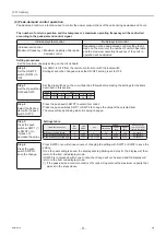
2. Defrost
end
Defrost-start conditions 1
1) Three minutes have passed since the compressor started
up.
2) Forty-five minutes have passed since the unit received an
operation command signal.
3) Cumulative compressor operation time after the completion
of the last defrost cycle has reached 45 minutes.
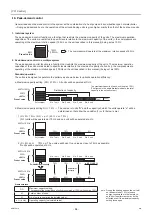
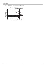
4) The air-side heat exchanger inlet temperature is equal to or
below the defrost-start temperature. (See the figure at right.)
5) Inlet water temperature is above 18ºC.
6) No other circuits are in the defrost cycle.
Defrost-start conditions 2
1) Twenty minutes have passed since the unit received an operation command signal.
2) Cumulative compressor operation time after the completion of the last defrost cycle has reached 20 minutes.
3) Air-side heat exchanger inlet temperature is below -31ºC.
4) Inlet water temperature is above 18ºC.
Defrost-start conditions 3
1) Three minutes have passed since the compressor started up.
2) Forty-five minutes have passed since the unit received an operation command signal.
3) Cumulative compressor operation time after the completion of the last defrost cycle has reached 240 minutes.
4) Air-side heat exchanger inlet temperature is equal to or below 0 ºC.
5) Inlet water temperature is above 18 ºC.
6) No other circuits are in the defrost cycle.
-30
-25
-20
-15
-10
-5
0
-20
-15
-10
-5
0
5
10
15
Outside temp. (°CDB)
Air-side HEX inlet temp.(°C )
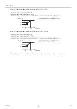
The defrost cycle will end when one of the following conditions is
met.
Whether the defrost-end condition is met is determined individu-
ally for each circuit.
1) An air-side heat exchanger inlet temperature of 15ºC or
above has been detected for 120 seconds.
2) An air-side heat exchanger inlet temperature of 25ºC or
above was detected.
3) Ten seconds have passed since the beginning of the defrost
cycle or later, the high-pressure has reached 3.0 MPa or
above.
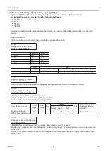
4) The inlet or outlet water temperature has dropped below the
value obtained by the following formula: Compressor fre-
quency during operation × 0.5 - 22 (ºC).
5) Twelve minutes have passed since the beginning of the de-
frost start (20 minutes, if the defrost operation is performed
at the defrost-start setting 2).
6) When the operation command signal is off.
10
60
65
70
75
80
85
90
95
100
15
20
25
30
Compressor frequency (Hz)
Defrost-end water temperature (°C )
0000001906.book 90 ページ 2015年11月5日 木曜日 午前11時55分
Summary of Contents for CAHV-P500YB-HPB
Page 1: ......
Page 7: ...CONTENTS HWE15070 GB ...
Page 9: ... 2 HWE15070 GB ...
Page 19: ... 12 HWE15070 GB ...
Page 37: ... 30 II Restrictions GB HWE15070 ...
Page 39: ... 32 HWE15070 GB ...
Page 48: ... 41 HWE15070 GB IV Remote Controller 1 Using the Remote Controller 43 2 Function Settings 48 ...
Page 49: ... 42 HWE15070 GB ...
Page 57: ... IV Remote Controller 50 HWE15070 GB ...
Page 58: ... 51 HWE15070 GB V Electrical Wiring Diagram 1 Electrical Wiring Diagram 53 ...
Page 59: ... 52 HWE15070 GB ...
Page 65: ... 58 V Electrical Wiring Diagram GB HWE15070 ...
Page 67: ... 60 HWE15070 GB ...
Page 71: ... VI Refrigerant Circuit 64 HWE15070 GB ...
Page 73: ... 66 HWE15070 GB ...
Page 111: ... 104 HWE15070 GB ...
Page 117: ... VIII Test Run Mode 110 HWE15070 GB ...
Page 119: ... 112 HWE15070 GB ...
Page 163: ... IX Troubleshooting 156 HWE15070 GB ...
Page 164: ... 157 HWE15070 GB X Attachments 1 R407C saturation temperature table 159 ...
Page 165: ... 158 HWE15070 GB ...
Page 167: ... X Attachments 160 HWE15070 GB ...
Page 168: ......

