[
II
Restrictions ]
- 13 -
HWE15070
GB
II
Restrictions
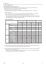
[1] System Configuration
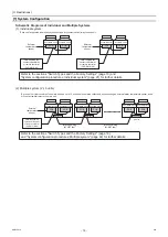
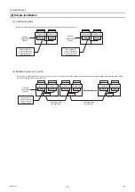
(1) Individual system
Schematic Diagrams of Individual and Multiple Systems
(2) Multiple system (2-16 units)
Refer to the sections "Switch Types and the Factory Settings" (page 18) and
"System configuration procedures: Individual system" (page 21) for further details.
Refer to the sections "Switch Types and the Factory Settings" (page 18)
and "System configuration procedures: Multiple system" (page 22) for further details.
Unit (MAIN circuit)
PCB
Unit (SUB circuit)
PCB
External
temperature
sensor
Field-supplied dry
contact switch/relay
or remote controller
(PAR-W21MAA)
Field-supplied dry
contact switch/relay
or remote controller
(PAR-W21MAA)
External
temperature
sensor
Unit (MAIN circuit)
PCB
Unit (SUB circuit)
PCB
*Each unit is operated individually by connecting a dry contact switch/relay to each unit.
External
temperature
sensor
Field-supplied dry
contact switch/relay
or remote controller
(PAR-W21MAA)
MAIN unit
SUB unit
SUB unit(s)
n units
Inter-unit wiring
(M-NET line)
Inter-unit wiring
(M-NET line)
Unit (MAIN circuit)
PCB
Unit (SUB circuit)
PCB
Unit (MAIN circuit)
PCB
Unit (SUB circuit)
PCB
Unit (MAIN circuit)
PCB
Unit (SUB circuit)
PCB
*A group of unit that consists of one main unit and up to 15 sub units is operated collectively by connecting an external water temperature sensor and a
dry contact switch/relay to the main unit.
0000001906.book 13 ページ 2015年11月5日 木曜日 午前11時55分
Summary of Contents for CAHV-P500YB-HPB
Page 1: ......
Page 7: ...CONTENTS HWE15070 GB ...
Page 9: ... 2 HWE15070 GB ...
Page 19: ... 12 HWE15070 GB ...
Page 37: ... 30 II Restrictions GB HWE15070 ...
Page 39: ... 32 HWE15070 GB ...
Page 48: ... 41 HWE15070 GB IV Remote Controller 1 Using the Remote Controller 43 2 Function Settings 48 ...
Page 49: ... 42 HWE15070 GB ...
Page 57: ... IV Remote Controller 50 HWE15070 GB ...
Page 58: ... 51 HWE15070 GB V Electrical Wiring Diagram 1 Electrical Wiring Diagram 53 ...
Page 59: ... 52 HWE15070 GB ...
Page 65: ... 58 V Electrical Wiring Diagram GB HWE15070 ...
Page 67: ... 60 HWE15070 GB ...
Page 71: ... VI Refrigerant Circuit 64 HWE15070 GB ...
Page 73: ... 66 HWE15070 GB ...
Page 111: ... 104 HWE15070 GB ...
Page 117: ... VIII Test Run Mode 110 HWE15070 GB ...
Page 119: ... 112 HWE15070 GB ...
Page 163: ... IX Troubleshooting 156 HWE15070 GB ...
Page 164: ... 157 HWE15070 GB X Attachments 1 R407C saturation temperature table 159 ...
Page 165: ... 158 HWE15070 GB ...
Page 167: ... X Attachments 160 HWE15070 GB ...
Page 168: ......

