[
II
Restrictions ]
- 25 -
HWE15070
GB
[7] Water Pipe Installation
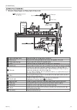
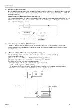
1. Schematic Piping Diagram and Piping System Components
6
Required to allow for a replacement of equipment.
Required to check the performance and monitor the operation of the units.
Recommended for checking the operation status.
Required to allow for a replacement or cleaning of the flow adjuster.
Recommended to prevent the noise and vibration from the pump from being transmitted.
Install the drain pipe with a downward inclination of between 1/100 and 1/200. To
prevent drain water from freezing in winter, install the drain pipe as steep an angle as
practically possible and minimize the straight line.
For cold climate installation, take an appropriate measure (e.g., drain heater) to prevent
the drain water from freezing.
Use a pump that is large enough to compensate for the total water pressure loss and
supply sufficient water to the unit.
Install air venting valves to the places where air can accumulate.
Automatic air vent valves (such as
') are effective.
Install an expansion tank to accommodate expanded water and to supply water.
Use pipes that allow for easy air purging, and provide adequate insulation.
Install drain valves so that water can be drained for servicing.
Install a strainer near the unit to keep foreign materials from entering the water-side
head exchanger (supplied).
Required to protect the unit.
Union joints/flange joints
Thermometer
Water pressure gauge
Valve
Flexible joint
Drain pipe
Pump
Air vent valve
Expansion tank
Water pipe
Drain valve
Strainer
Flow switch
indicates the direction of
the water flow.
Heat pump unit
Water-side
heat
exchanger
City water
Overflowed water
To drain outlet
Minimum upward
gradient of 1/200
Minimum upward
gradient of 1/200
Access hole cover
To drain outlet
Air conditioning unit
P
P
P
T
T
5
5
3
8 '
4
1
1
1
6
7
5
4
4
3
11
2
12
1
3
4
8
2
1
1
9
1
13
4
4
11
8
1
2
3
4
5
7
8
9
10
11
12
13
6
0000001906.book 25 ページ 2015年11月5日 木曜日 午前11時55分
Summary of Contents for CAHV-P500YB-HPB
Page 1: ......
Page 7: ...CONTENTS HWE15070 GB ...
Page 9: ... 2 HWE15070 GB ...
Page 19: ... 12 HWE15070 GB ...
Page 37: ... 30 II Restrictions GB HWE15070 ...
Page 39: ... 32 HWE15070 GB ...
Page 48: ... 41 HWE15070 GB IV Remote Controller 1 Using the Remote Controller 43 2 Function Settings 48 ...
Page 49: ... 42 HWE15070 GB ...
Page 57: ... IV Remote Controller 50 HWE15070 GB ...
Page 58: ... 51 HWE15070 GB V Electrical Wiring Diagram 1 Electrical Wiring Diagram 53 ...
Page 59: ... 52 HWE15070 GB ...
Page 65: ... 58 V Electrical Wiring Diagram GB HWE15070 ...
Page 67: ... 60 HWE15070 GB ...
Page 71: ... VI Refrigerant Circuit 64 HWE15070 GB ...
Page 73: ... 66 HWE15070 GB ...
Page 111: ... 104 HWE15070 GB ...
Page 117: ... VIII Test Run Mode 110 HWE15070 GB ...
Page 119: ... 112 HWE15070 GB ...
Page 163: ... IX Troubleshooting 156 HWE15070 GB ...
Page 164: ... 157 HWE15070 GB X Attachments 1 R407C saturation temperature table 159 ...
Page 165: ... 158 HWE15070 GB ...
Page 167: ... X Attachments 160 HWE15070 GB ...
Page 168: ......


