[
V
Electrical Wiring Diagram ]
- 55 -
HWE15070
GB
Note
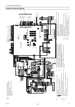
C100
R5
Electrical resistance
R1
High pressure sensor
63HS
Fan motor
Drain pan heater
<
H21
>
Emargency signal (for extra heater)
<
H20
>
Solenoid valve(Hot gas circuit)
SV2
LEV1
Electronic expansion valve(Injection)
Electromagnetic relay(Inverter main circuit)
72C
DC reactor
DCL
Pump motor
Fuse
Electromagnetic contactor(Pump)
Overcurrent relay(Pump)
Earth leakage breaker
<
MP
>
<
F2
>
<
52P
>
<
51P
>
<
ELB1,2
>
Thermistor
Electronic expansion valve(Main circuit)
Fuse
63H1
TH12,13
TH5
~
8
High pressure switch
Solenoid valve(Injection circuit)
4-way valve
Low pressure sensor
Crankcase heater(for heating the compressor)
Thermistor
Compressor motor
MS
M
TH1
~
4
TH14
~
16
TH9
,
11
63LS
CH
LEV2
21S4
SV1
Ac current sensor
Capacitor(Electrolysis)
F06
F05
F04
F03
F02
F01
CT3
CT22
CT12
MAIN BOX
SUB BOX
Field-
supplied
MAIN BOX
and
SUB BOX
Symbol explanation
explanation
Symbol
Function setting connector
Z21
IGBT
temperature
THHS
3. Use a contact that takes 12VDC 5mA
for no-voltage contact input.
1. Make sure to connect a pump interlock contact.
A
short-circuit may cause abnormal stop or malfunctions.
2.
The preset temperature setting can be switched from the no-voltage contact
or by setting time ranges.
0000001906.book 55 ページ 2015年11月5日 木曜日 午前11時55分
Summary of Contents for CAHV-P500YB-HPB
Page 1: ......
Page 7: ...CONTENTS HWE15070 GB ...
Page 9: ... 2 HWE15070 GB ...
Page 19: ... 12 HWE15070 GB ...
Page 37: ... 30 II Restrictions GB HWE15070 ...
Page 39: ... 32 HWE15070 GB ...
Page 48: ... 41 HWE15070 GB IV Remote Controller 1 Using the Remote Controller 43 2 Function Settings 48 ...
Page 49: ... 42 HWE15070 GB ...
Page 57: ... IV Remote Controller 50 HWE15070 GB ...
Page 58: ... 51 HWE15070 GB V Electrical Wiring Diagram 1 Electrical Wiring Diagram 53 ...
Page 59: ... 52 HWE15070 GB ...
Page 65: ... 58 V Electrical Wiring Diagram GB HWE15070 ...
Page 67: ... 60 HWE15070 GB ...
Page 71: ... VI Refrigerant Circuit 64 HWE15070 GB ...
Page 73: ... 66 HWE15070 GB ...
Page 111: ... 104 HWE15070 GB ...
Page 117: ... VIII Test Run Mode 110 HWE15070 GB ...
Page 119: ... 112 HWE15070 GB ...
Page 163: ... IX Troubleshooting 156 HWE15070 GB ...
Page 164: ... 157 HWE15070 GB X Attachments 1 R407C saturation temperature table 159 ...
Page 165: ... 158 HWE15070 GB ...
Page 167: ... X Attachments 160 HWE15070 GB ...
Page 168: ......

