[
II
Restrictions ]
- 28 -
HWE15070
GB
3. Installing
the
strainer and flow switch
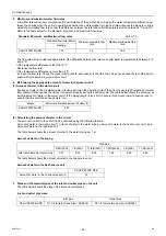
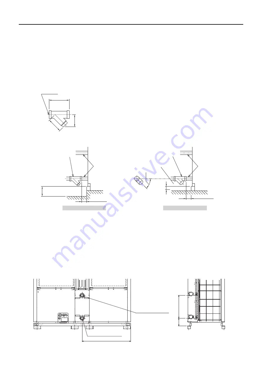
4. Water pipe hole size and location
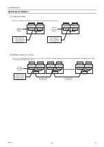
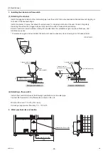
(1) Installing the strainer
Install the supplied strainer on the inlet water pipe near the unit to filter out suspended solids and prevent clogging or
corrosion of the heat exchanger.
Install the strainer in a way that allows for easy access for cleaning, and instruct the user to clean it regularly.
Operating the units with a clogged strainer may cause the units to make an abnormal stop.
Select a location to install a strainer, taking into consideration the installation angle, insulation thickness, and
maintenance space.
* The dimensions given below indicate the amount of space necessary when screwing in a Y-shaped strainer.
(2) Installing a flow switch
Install a flow switch that meets the following specifications on the water pipe.
Connect the flow switch to the flow switch contact on the unit.
Minimum flow rate= 7.5 m³/h (125 L/min)
Unit usage range (water flow rate): 7.5 - 15.0 m³/h
Rc1 1/2
160
11
5
10
0
Y-shaped strainer
(supplied)
Pipes
(field-supplied)
Min. 110
Y-shaped strainer
maintenance access space
153
Sample installation 1
Sample installation 2
Min. 110
* Mi
n.
43
Max. 25º
Y-shaped strainer
maintenance access space
Y-shaped strainer
(supplied)
Pipes (field-supplied)
<Unit: mm>
Water inlet <Rc1-1/2B>
Water outlet <Rc1-1/2B>
989
466
155
0000001906.book 28 ページ 2015年11月5日 木曜日 午前11時55分
Summary of Contents for CAHV-P500YB-HPB
Page 1: ......
Page 7: ...CONTENTS HWE15070 GB ...
Page 9: ... 2 HWE15070 GB ...
Page 19: ... 12 HWE15070 GB ...
Page 37: ... 30 II Restrictions GB HWE15070 ...
Page 39: ... 32 HWE15070 GB ...
Page 48: ... 41 HWE15070 GB IV Remote Controller 1 Using the Remote Controller 43 2 Function Settings 48 ...
Page 49: ... 42 HWE15070 GB ...
Page 57: ... IV Remote Controller 50 HWE15070 GB ...
Page 58: ... 51 HWE15070 GB V Electrical Wiring Diagram 1 Electrical Wiring Diagram 53 ...
Page 59: ... 52 HWE15070 GB ...
Page 65: ... 58 V Electrical Wiring Diagram GB HWE15070 ...
Page 67: ... 60 HWE15070 GB ...
Page 71: ... VI Refrigerant Circuit 64 HWE15070 GB ...
Page 73: ... 66 HWE15070 GB ...
Page 111: ... 104 HWE15070 GB ...
Page 117: ... VIII Test Run Mode 110 HWE15070 GB ...
Page 119: ... 112 HWE15070 GB ...
Page 163: ... IX Troubleshooting 156 HWE15070 GB ...
Page 164: ... 157 HWE15070 GB X Attachments 1 R407C saturation temperature table 159 ...
Page 165: ... 158 HWE15070 GB ...
Page 167: ... X Attachments 160 HWE15070 GB ...
Page 168: ......

