


Mic amp input gain (preliminary input processing)
267
PRO6 Live Audio System
Owner’s Manual
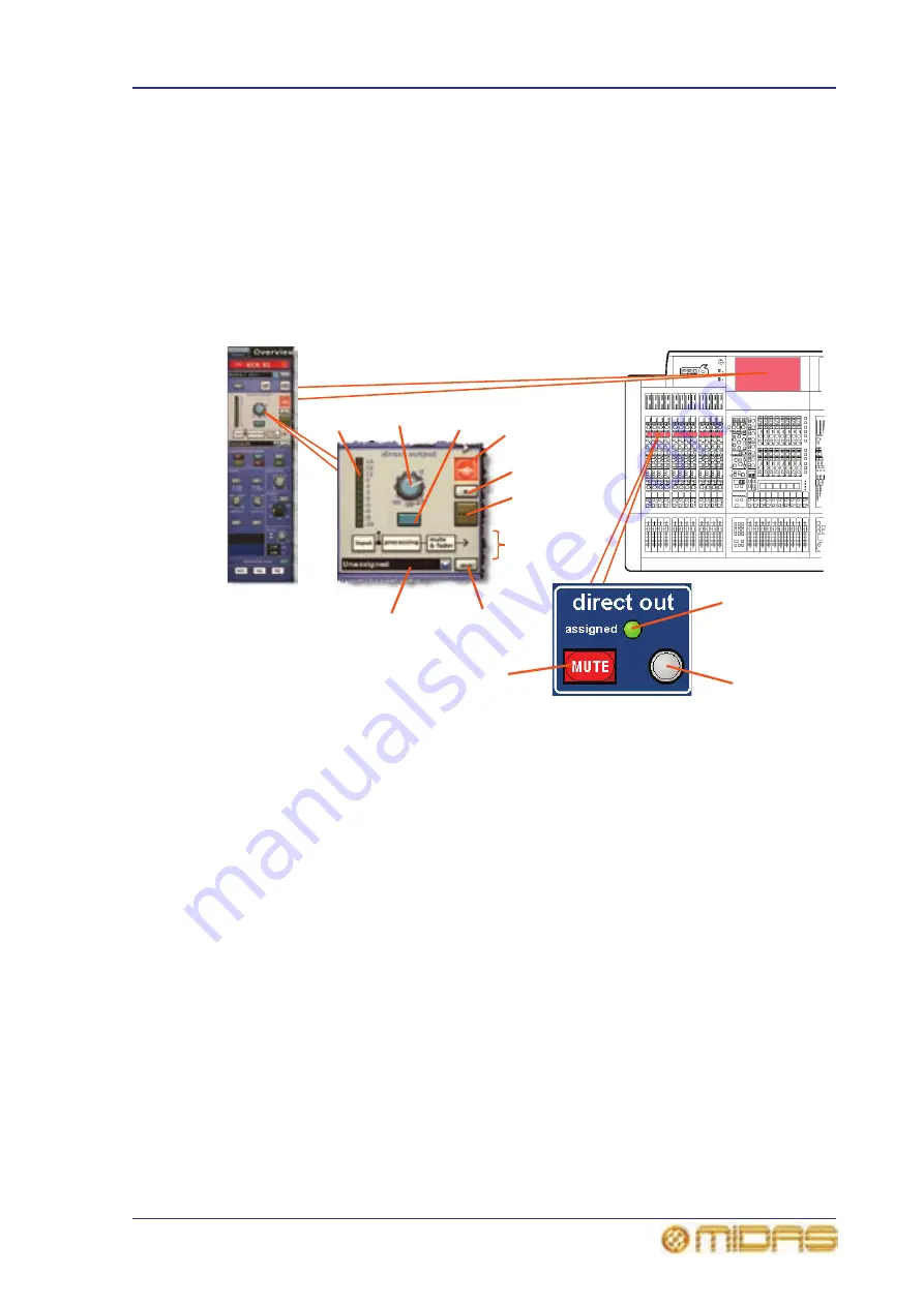
Direct output
The direct output section provides an internal connection to effects etc. or a way of
leaving the control centre via an I/O box. It allows you to take a signal directly out of a
defined point in the input channel’s signal path and route it to either an internal
assignable effect or a physical output (a physical connection at one of the line I/O
boxes). This function is optional and assigned on a channel-by-channel basis.
This section is deliberately distanced from the main channel panel controls because it is
a limited resource and unused on many channels.
Selection of signal path position (item 4) and destination (item 5) can only be carried
out via the GUI.
1
2
3
8
4
7
6
3
11
1
9
10
1
MUTE switch, mutes any assigned direct
output by removing signal from the output.
However, it will not operate (will remain
illuminated) if nothing is assigned. It is
included in the scene recall system but is not
affected by the channel mute safe or the auto-
mute masters (unless the source tap-off point
is after the main channel mute).
2
Solo B switch, changes the operation of
the SOLO switch so that it routes signals to the
monitor B section of the control centre.
3
SOLO switch, activates signal routing to
the Monitor A section of the control centre.
4
Tap-off point diagram, shows where the
direct output is sourced from in the signal
path, as selected by the mode button (see
item 6).
5
dest button, opens the Patching screen
so that you can select the destination of the
direct output.
6
Mode button, changes the source tap-off
point for the signal. There are three options:
post-fader and mute; pre-mute and
post-processing; or pre-mute and
pre-processing. This function is not used if the
direct output is not unassigned to channel.
7
10-LED meter, monitors the direct output
level in the range +18dB to -36dB.
8
Control knob, adjusts direct output level.
Range is infinity (
∞
) to 10dB.
9
assigned LED, illuminates when a direct
output is in use.
10
Quick access button, selects the channel
and assigns the configuration processing area
to the GUI channel strip.
11
Direct output drop-down list, for
displaying the destination(s) of the direct
output. For example, to an O/B vehicle, while
simultaneously going into a DN9696.
Summary of Contents for PRO6
Page 2: ......
Page 4: ......
Page 6: ......
Page 10: ......
Page 14: ...xvi Precautions PRO6 Live Audio System Owner s Manual...
Page 24: ...xxvi Contents PRO6 Live Audio System Owner s Manual...
Page 25: ...PRO6 Live Audio System Owner s Manual Volume 1 Overview...
Page 26: ......
Page 30: ...4 Chapter 1 Introduction PRO6 Live Audio System Owner s Manual...
Page 42: ...16 Chapter 2 PRO6 Live Audio System PRO6 Live Audio System Owner s Manual...
Page 50: ...24 Chapter 3 About The PRO6 Control Centre PRO6 Live Audio System Owner s Manual...
Page 51: ...PRO6 Live Audio System Owner s Manual Volume 1 Getting Started...
Page 52: ......
Page 59: ...PRO6 Live Audio System Owner s Manual Volume 2 Basic Operation Of The PRO6...
Page 60: ......
Page 64: ...38 Chapter 5 Before You Start PRO6 Live Audio System Owner s Manual...
Page 104: ...78 Chapter 8 Patching PRO6 Live Audio System Owner s Manual...
Page 131: ...PRO6 Live Audio System Owner s Manual Volume 3 Advanced Operation And Features...
Page 132: ......
Page 136: ...110 Chapter 10 Stereo Linking PRO6 Live Audio System Owner s Manual...
Page 144: ...118 Chapter 11 Panning PRO6 Live Audio System Owner s Manual...
Page 148: ...122 Chapter 12 Soloing PRO6 Live Audio System Owner s Manual...
Page 150: ...124 Chapter 13 Muting PRO6 Live Audio System Owner s Manual...
Page 192: ...166 Chapter 18 Copy And Paste PRO6 Live Audio System Owner s Manual...
Page 242: ...216 Chapter 24 User Libraries Presets PRO6 Live Audio System Owner s Manual...
Page 246: ...220 Chapter 25 File Management PRO6 Live Audio System Owner s Manual...
Page 250: ...224 Chapter 26 Using Other Devices With The PRO6 PRO6 Live Audio System Owner s Manual...
Page 267: ...PRO6 Live Audio System Owner s Manual Volume 4 Description...
Page 268: ......
Page 335: ...PRO6 Live Audio System Owner s Manual Volume 5 Appendices...
Page 336: ......
Page 365: ...Audio signal path 339 PRO6 Live Audio System Owner s Manual Audio signal path...
Page 366: ...340 Appendix C Klark Teknik DN370 GEQ PRO6 Live Audio System Owner s Manual...
Page 372: ...346 Appendix D Klark Teknik DN780 Reverb PRO6 Live Audio System Owner s Manual...
Page 376: ...350 Appendix E I O Modules PRO6 Live Audio System Owner s Manual...
Page 400: ...374 Appendix I Documentation PRO6 Live Audio System Owner s Manual...
Page 511: ...Return 485 XL8 Live Performance System Owner s Manual Gate Not applicable EQ Not applicable...
Page 612: ...586 Glossary PRO6 Live Audio System Owner s Manual...


