


2
Chapter 1: Introduction
PRO6 Live Audio System
Owner’s Manual
Conventions
• Hand symbols, such as,
(pushbutton, trackball etc.) and
(control knob), are
used to show the operation of the physical controls on the control surface. GUI
operation is indicated by a pointer
, which represents a ‘click’ operation.
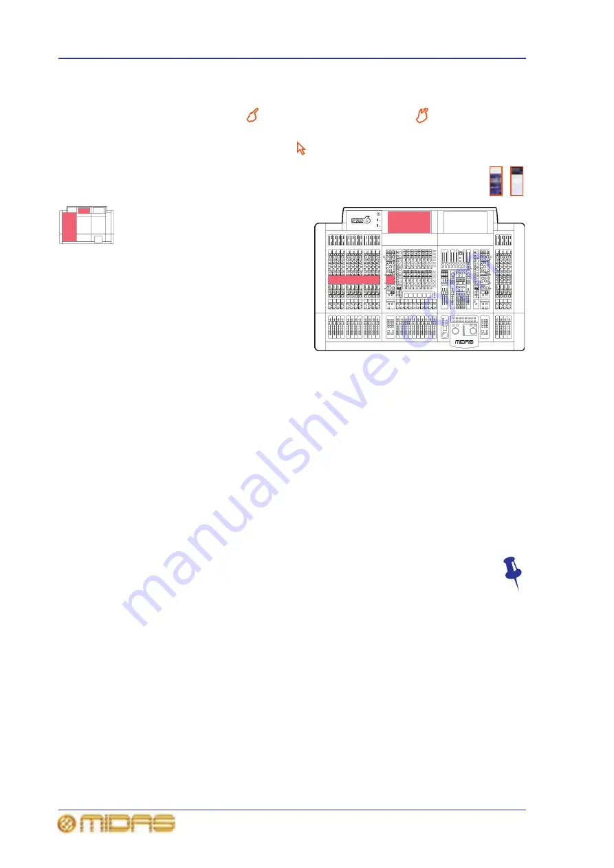
• The graphics shown right are used to differentiate between diagrams of
the control surface (immediate right) and GUI (far right). Placement is
generally towards the upper-right corner of the diagram.
• ‘Outline drawings are strategically
placed throughout the manual to
reference information to the
appropriate area(s) on the control
surface/GUI of the PRO6 Control
Centre. The small version (left)
indicates bay and GUI location, while
the larger, more accurate one can
pinpoint control sections (for
example, the EQ areas of the
12-channel input bay shown right).
Target areas are shaded in red.
• Unless otherwise stated, illumination
of a control (pushbutton, switch, control knob etc.) on the control surface/GUI of the
PRO6 Control Centre indicates an “on”, “active” or “enabled” state. Conversely, an
extinguished condition indicates the control is “off”, “inactive” or “disabled”.
• The following types of pushbutton are used on the control surface:
• “switch” - a latching pushbutton, that is, one that changes its on/off status.
• “button” - a non-latching pushbutton.
• “key” - a keyboard-type pushbutton. Usually used for entering data, such as a
number or character.
• Generally, control names are the same whether they are on the control surface or
the GUI. However, in cases where they differ, both names will be given, separated
by a forward slash “/”. The control name shown on the GUI will always be last and
enclosed in square brackets “[]”. For example, MENU/[S/C], which is the button
used for accessing the Select Side-Chain Source window (see “Side chain” on
page 273).
• Hints and tips, which convey useful information to the user, appear where you
see the drawing pin graphic (shown right).
Terminology
To support both FOH and MON use, the terminology has been chosen very carefully to
apply equally to both (see "Glossary" on page 579). For a definition of the PRO6’s
primary buses, see “Definition of the primary buses” on page 375.
Summary of Contents for PRO6
Page 2: ......
Page 4: ......
Page 6: ......
Page 10: ......
Page 14: ...xvi Precautions PRO6 Live Audio System Owner s Manual...
Page 24: ...xxvi Contents PRO6 Live Audio System Owner s Manual...
Page 25: ...PRO6 Live Audio System Owner s Manual Volume 1 Overview...
Page 26: ......
Page 30: ...4 Chapter 1 Introduction PRO6 Live Audio System Owner s Manual...
Page 42: ...16 Chapter 2 PRO6 Live Audio System PRO6 Live Audio System Owner s Manual...
Page 50: ...24 Chapter 3 About The PRO6 Control Centre PRO6 Live Audio System Owner s Manual...
Page 51: ...PRO6 Live Audio System Owner s Manual Volume 1 Getting Started...
Page 52: ......
Page 59: ...PRO6 Live Audio System Owner s Manual Volume 2 Basic Operation Of The PRO6...
Page 60: ......
Page 64: ...38 Chapter 5 Before You Start PRO6 Live Audio System Owner s Manual...
Page 104: ...78 Chapter 8 Patching PRO6 Live Audio System Owner s Manual...
Page 131: ...PRO6 Live Audio System Owner s Manual Volume 3 Advanced Operation And Features...
Page 132: ......
Page 136: ...110 Chapter 10 Stereo Linking PRO6 Live Audio System Owner s Manual...
Page 144: ...118 Chapter 11 Panning PRO6 Live Audio System Owner s Manual...
Page 148: ...122 Chapter 12 Soloing PRO6 Live Audio System Owner s Manual...
Page 150: ...124 Chapter 13 Muting PRO6 Live Audio System Owner s Manual...
Page 192: ...166 Chapter 18 Copy And Paste PRO6 Live Audio System Owner s Manual...
Page 242: ...216 Chapter 24 User Libraries Presets PRO6 Live Audio System Owner s Manual...
Page 246: ...220 Chapter 25 File Management PRO6 Live Audio System Owner s Manual...
Page 250: ...224 Chapter 26 Using Other Devices With The PRO6 PRO6 Live Audio System Owner s Manual...
Page 267: ...PRO6 Live Audio System Owner s Manual Volume 4 Description...
Page 268: ......
Page 335: ...PRO6 Live Audio System Owner s Manual Volume 5 Appendices...
Page 336: ......
Page 365: ...Audio signal path 339 PRO6 Live Audio System Owner s Manual Audio signal path...
Page 366: ...340 Appendix C Klark Teknik DN370 GEQ PRO6 Live Audio System Owner s Manual...
Page 372: ...346 Appendix D Klark Teknik DN780 Reverb PRO6 Live Audio System Owner s Manual...
Page 376: ...350 Appendix E I O Modules PRO6 Live Audio System Owner s Manual...
Page 400: ...374 Appendix I Documentation PRO6 Live Audio System Owner s Manual...
Page 511: ...Return 485 XL8 Live Performance System Owner s Manual Gate Not applicable EQ Not applicable...
Page 612: ...586 Glossary PRO6 Live Audio System Owner s Manual...


