


130
Chapter 14: Monitors And Communications
PRO6 Live Audio System
Owner’s Manual
• PFL switch, sends mono pre-fader listen (PFL) solo bus signals to headphones and
local monitor outputs. With PFL switch disabled (LED extinguished), stereo after
fader listen (AFL) solo bus signals are sent to headphones and local monitor outputs.
• ADD switch, allows multiple channel access to solo buses. When solo add mode is
off, pressing a solo switch cancels any currently active solos. Multiple solos, for
example, stereo left and right signals, can be monitored in this mode provided solo
switches are pressed at approximately the same time. When solo add mode is on,
auto-cancelling is defeated, which allows multiple channel or output soloing. In this
mode, input solos have priority over output solos and VCA solos, and will temporarily
override them. When input solo is cancelled, output solo or VCA solos will return.
• CLEAR switch, illuminates when a solo switch is active in its monitor section and,
when pressed, clears any solo switches in that section.
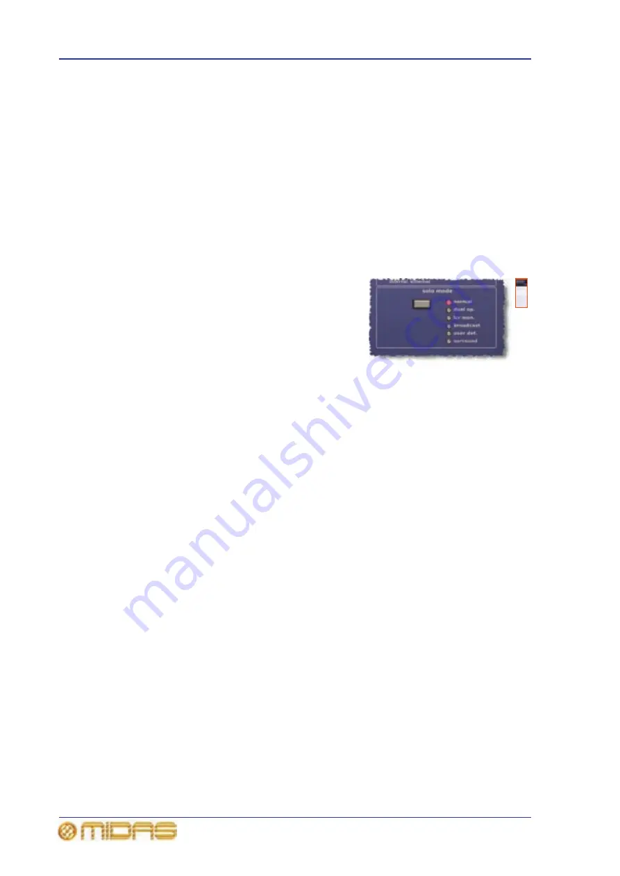
solo mode section (GUI only)
On the GUI, the solo mode section has a select
button by which you can cycle through the solo
mode options to select the one you want. Each
option has an LED that illuminates when its option
is selected.
The options are as follows:
• normal — both solo systems, A and B, are
active and behave as a single solo system.
• dual op. — in dual operator mode, both solo systems (A and B) are totally
independent of each other. The solo B button, in addition to routing the soloed
material to monitoring system B, determines which set of PFL, ADD and CLEAR
controls (see “solo (a and b) sections” on page 129) are applied to the solo.
• lcr mon. — left-centre-right monitor mode is similar to normal mode, but when
nothing is being soloed the left and right masters are routed to the monitor A output
and the mono master is routed to the monitor B output.
Pressing any solo switch on the control centre temporarily overrides the selected
primary source selection, while the talk assignment is unaffected (this signal is
summed further down the signal path, so as not to affect the monitor meters).
Each mode changes interleaving logic between different areas of monitor output.
• broadcast — routes stereo masters to the monitor A output and activates all the
solo B controls so that soloed material is routed to the monitor B outputs. This
allows the master outputs to be continually broadcast (probably the on-air
program), while the other material is soloed.
• user def. — in user-defined mode, you can set up the monitoring system. These
settings are recalled on return to this mode after using one of the other solo modes,
for example, normal mode or broadcast mode. (User defined monitor settings are
not stored in scenes or show files.)
• surround — all levels are controlled from the channel A fader.
Summary of Contents for PRO6
Page 2: ......
Page 4: ......
Page 6: ......
Page 10: ......
Page 14: ...xvi Precautions PRO6 Live Audio System Owner s Manual...
Page 24: ...xxvi Contents PRO6 Live Audio System Owner s Manual...
Page 25: ...PRO6 Live Audio System Owner s Manual Volume 1 Overview...
Page 26: ......
Page 30: ...4 Chapter 1 Introduction PRO6 Live Audio System Owner s Manual...
Page 42: ...16 Chapter 2 PRO6 Live Audio System PRO6 Live Audio System Owner s Manual...
Page 50: ...24 Chapter 3 About The PRO6 Control Centre PRO6 Live Audio System Owner s Manual...
Page 51: ...PRO6 Live Audio System Owner s Manual Volume 1 Getting Started...
Page 52: ......
Page 59: ...PRO6 Live Audio System Owner s Manual Volume 2 Basic Operation Of The PRO6...
Page 60: ......
Page 64: ...38 Chapter 5 Before You Start PRO6 Live Audio System Owner s Manual...
Page 104: ...78 Chapter 8 Patching PRO6 Live Audio System Owner s Manual...
Page 131: ...PRO6 Live Audio System Owner s Manual Volume 3 Advanced Operation And Features...
Page 132: ......
Page 136: ...110 Chapter 10 Stereo Linking PRO6 Live Audio System Owner s Manual...
Page 144: ...118 Chapter 11 Panning PRO6 Live Audio System Owner s Manual...
Page 148: ...122 Chapter 12 Soloing PRO6 Live Audio System Owner s Manual...
Page 150: ...124 Chapter 13 Muting PRO6 Live Audio System Owner s Manual...
Page 192: ...166 Chapter 18 Copy And Paste PRO6 Live Audio System Owner s Manual...
Page 242: ...216 Chapter 24 User Libraries Presets PRO6 Live Audio System Owner s Manual...
Page 246: ...220 Chapter 25 File Management PRO6 Live Audio System Owner s Manual...
Page 250: ...224 Chapter 26 Using Other Devices With The PRO6 PRO6 Live Audio System Owner s Manual...
Page 267: ...PRO6 Live Audio System Owner s Manual Volume 4 Description...
Page 268: ......
Page 335: ...PRO6 Live Audio System Owner s Manual Volume 5 Appendices...
Page 336: ......
Page 365: ...Audio signal path 339 PRO6 Live Audio System Owner s Manual Audio signal path...
Page 366: ...340 Appendix C Klark Teknik DN370 GEQ PRO6 Live Audio System Owner s Manual...
Page 372: ...346 Appendix D Klark Teknik DN780 Reverb PRO6 Live Audio System Owner s Manual...
Page 376: ...350 Appendix E I O Modules PRO6 Live Audio System Owner s Manual...
Page 400: ...374 Appendix I Documentation PRO6 Live Audio System Owner s Manual...
Page 511: ...Return 485 XL8 Live Performance System Owner s Manual Gate Not applicable EQ Not applicable...
Page 612: ...586 Glossary PRO6 Live Audio System Owner s Manual...


