


84
Chapter 9: Basic Operation
PRO6 Live Audio System
Owner’s Manual
Using VCA/POP groups
VCA/POP groups (bottom of the mix bay) allow simultaneous control over a number of
channels. This provides a quick method of bringing particular channels to the control
surface and saves you having to remember their name/number. You can choose
channel group associations and also configure the colour and legend of each group’s
LCD select button to make them instantly recognisable. The LCD select button for each
group is used for both group member assignment and group recall.
Any group can have any channels (input/output) assigned to them, although in normal
practise is more likely that they will only have one or the other. Only input channel
group members are unfolded to the surface (input bays).
VCA groups include fader, solo and mute control, whereas POP groups are limited to
unfolding channels (on area A or B).
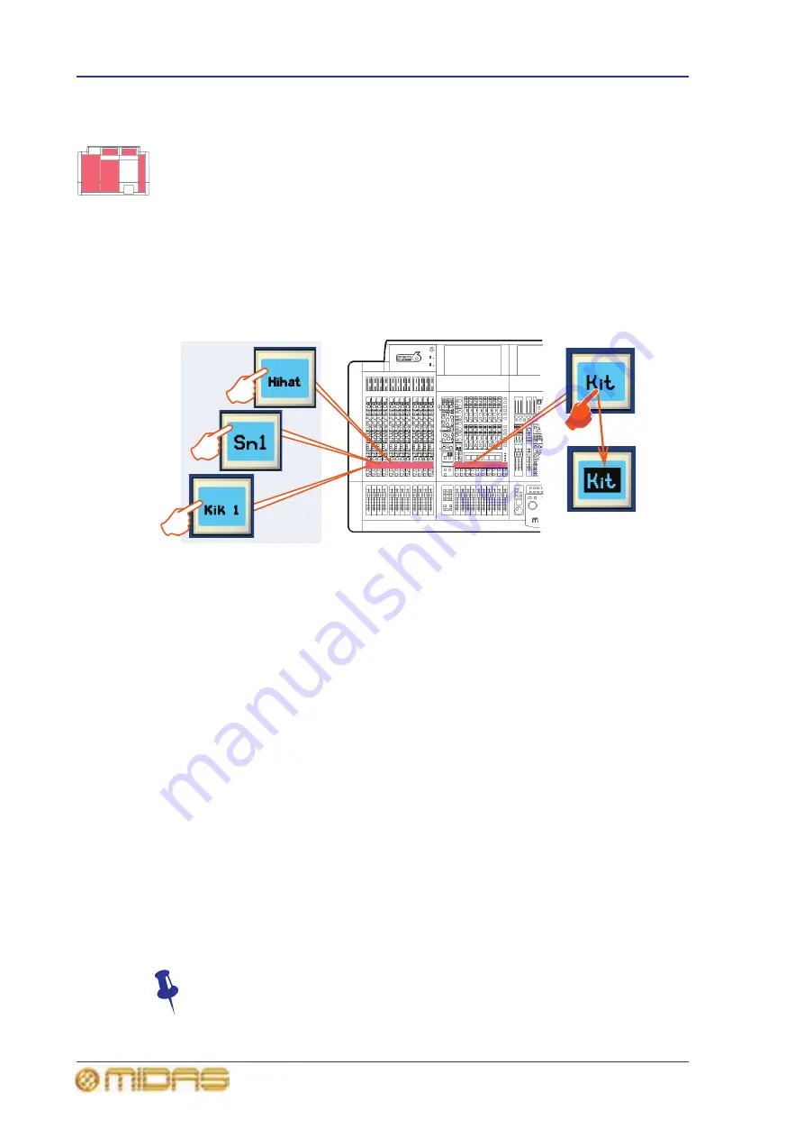
>> To assign channels to a VCA/POP group
1
Press and hold down the LCD select button of the desired group (VCA or POP).
For example, “Kit” in the VCAs (as shown above). The group’s LCD select button
will start flashing when you are in group member selection mode and the inputs
will jump to program mode. Any existing input channel group members will be
unfolded to the control surface.
2
While still holding down the LCD select button, do one of the following:
• To assign an input channel to the group, press the LCD select button of the
desired input channel. Repeat for any other input channels you want in the
group. For example, “Kik 1”, “Sn1”, “Hihat” and “Tom” (shown above). If
necessary scroll to a new bank of input channels. A bank LED (input select
section) will flash if it contains a channel that is a member of the current
group, and the bank is not at the control surface.
• To assign an output channel to the group, press the quick access button of the
desired output channel. Repeat for any other output channels you want in the
group. If necessary navigate the desired output channels to the control
surface. The quick access buttons of any output channels that are at the
control surface and are group members will illuminate. Individual output
select buttons will flash if their bank contains a member of the current group.
3
Release the group LCD select button. The group now contains the channel
members you have just assigned and the group will be selected.
4
To exit the group, quickly press the group LCD select button.
To quickly see which channels are in a particular VCA group, press its SOLO
button on and off. Monitor this action on the Meters display (master bay GUI).
Only the SOLO buttons of channels that are group members will be affected.
VCA group LCD
select button
Input channel
LCD select
buttons
Summary of Contents for PRO6
Page 2: ......
Page 4: ......
Page 6: ......
Page 10: ......
Page 14: ...xvi Precautions PRO6 Live Audio System Owner s Manual...
Page 24: ...xxvi Contents PRO6 Live Audio System Owner s Manual...
Page 25: ...PRO6 Live Audio System Owner s Manual Volume 1 Overview...
Page 26: ......
Page 30: ...4 Chapter 1 Introduction PRO6 Live Audio System Owner s Manual...
Page 42: ...16 Chapter 2 PRO6 Live Audio System PRO6 Live Audio System Owner s Manual...
Page 50: ...24 Chapter 3 About The PRO6 Control Centre PRO6 Live Audio System Owner s Manual...
Page 51: ...PRO6 Live Audio System Owner s Manual Volume 1 Getting Started...
Page 52: ......
Page 59: ...PRO6 Live Audio System Owner s Manual Volume 2 Basic Operation Of The PRO6...
Page 60: ......
Page 64: ...38 Chapter 5 Before You Start PRO6 Live Audio System Owner s Manual...
Page 104: ...78 Chapter 8 Patching PRO6 Live Audio System Owner s Manual...
Page 131: ...PRO6 Live Audio System Owner s Manual Volume 3 Advanced Operation And Features...
Page 132: ......
Page 136: ...110 Chapter 10 Stereo Linking PRO6 Live Audio System Owner s Manual...
Page 144: ...118 Chapter 11 Panning PRO6 Live Audio System Owner s Manual...
Page 148: ...122 Chapter 12 Soloing PRO6 Live Audio System Owner s Manual...
Page 150: ...124 Chapter 13 Muting PRO6 Live Audio System Owner s Manual...
Page 192: ...166 Chapter 18 Copy And Paste PRO6 Live Audio System Owner s Manual...
Page 242: ...216 Chapter 24 User Libraries Presets PRO6 Live Audio System Owner s Manual...
Page 246: ...220 Chapter 25 File Management PRO6 Live Audio System Owner s Manual...
Page 250: ...224 Chapter 26 Using Other Devices With The PRO6 PRO6 Live Audio System Owner s Manual...
Page 267: ...PRO6 Live Audio System Owner s Manual Volume 4 Description...
Page 268: ......
Page 335: ...PRO6 Live Audio System Owner s Manual Volume 5 Appendices...
Page 336: ......
Page 365: ...Audio signal path 339 PRO6 Live Audio System Owner s Manual Audio signal path...
Page 366: ...340 Appendix C Klark Teknik DN370 GEQ PRO6 Live Audio System Owner s Manual...
Page 372: ...346 Appendix D Klark Teknik DN780 Reverb PRO6 Live Audio System Owner s Manual...
Page 376: ...350 Appendix E I O Modules PRO6 Live Audio System Owner s Manual...
Page 400: ...374 Appendix I Documentation PRO6 Live Audio System Owner s Manual...
Page 511: ...Return 485 XL8 Live Performance System Owner s Manual Gate Not applicable EQ Not applicable...
Page 612: ...586 Glossary PRO6 Live Audio System Owner s Manual...


