


Using Protection Features
326
10.1.2
Overload Early Warning and Trip
A warning or fault trip (cutoff) occurs when the motor reaches an overload state, based on the
motor-rated current. The amount of current for warnings and trips can be set separately.
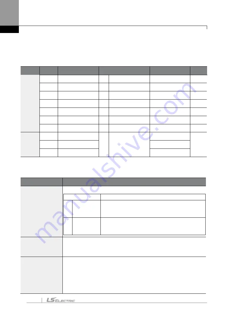
Group
Code
LCD Display
Parameter Setting
Setting Range
Unit
PRT
04
Load Duty
1
Heavy Duty
-
-
17
OL Warn Select
1
Yes
0
–
1
-
18
OL Warn Level
-
150
30
–
180
%
19
OL Warn Time
-
10.0
0
–
30
sec
20
OL Trip Select
1
Free-Run
-
-
21
OL Trip Level
-
180
30
–
200
%
22
OL Trip Time
-
60.0
0
–
60.0
sec
OUT
31
Relay 1
5
Over Load
-
-
32
Relay 2
-
33
Q1 Define
-
Overload Early Warning and Trip Setting Details
Code
Description
PRT-04 Load Duty
Select the load level.
Setting
Function
0 Normal
Duty
Use this setting for light loads, such as, fans and
pumps (overload tolerance: 110% of rated underload
current for 1 minute).
1 Heavy Duty
Use this setting for heavy loads, such as, cranes and
parking elevators (overload tolerance: 150% of rated
heavy load current for 1 minute).
PRT-17
OL Warn Select
If the overload reaches the warning level, the terminal block multi-function
output terminal and relay are used
to output a warning signal. If “1 (Yes)”
is
selected, it will operate. If “0 (No)”
is selected, it will not operate.
PRT-18
OL Warn Level,
PRT-19
OL Warn Time
When the input current to the motor is greater than the overload warning
level (OL Warn Level) and continues at that level during the overload
warning time (OL Warn Time), the multi-function output (Relay 1, Q1) sends
a warning signal. When Over Load is selected at OUT-31 and OUT-33, the
multi-function output terminal or relay outputs a signal. The signal output
does not block the inverter output.
Summary of Contents for SV-iS7 Series
Page 17: ......
Page 114: ...Peripheral Devices 97 Group 2 ...
Page 115: ...Peripheral Devices 98 Group 3 ...
Page 116: ...Peripheral Devices 99 Group 4 ...
Page 159: ...Basic Functions 142 Code Description V1 Quantizing ...
Page 465: ...Safety Funtion STO Safe Torque Off 448 14 2 1 Safety Function Wiring Diagram ...


