6. Description of Parameters
- 176 -
6
Ƶ
Droop Control
The droop control function aims at balancing the load level of two motors that drive
the same load. This function is required only when both master and slave are in speed
control.
A proper droop rate is gradually obtained during drive running. Therefore, do not set F8-
15 to a very large value. Otherwise, steady speed will decline obviously when load is very
large. You must set this parameter in both master and slave.
Figure 6-53 Relationship between droop rate and output torque
Droop rate
(%)
Output torque
(%)
0
100%
Ɣ
Droop speed = rated motor frequency x output torque x droop rate
Ɣ
Actual AC drive frequency = frequency reference - droop speed
Suppose that F8-15 is set to 10.0%, rated motor frequency is 50 Hz, and output torque is
50%. Actual drive frequency = 50 Hz – 50 x 50% x 10.0% = 47.5 Hz.
Note
Setting range 0.0% to 100.0% of F8-15 correspond to 0.00 to 10.00 on
operating panel.
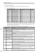
Function Code
Parameter Name
Setting Range
Default
A8-00
Point-point communication
0: Disabled
1: Enabled
0
This function parameter determines whether to enable point-point communication.
The point-point communication indicates direct communication between two or more
drives via CANlink. The master sends frequency or torque reference to slaves based on
frequency or torque signal it receives.
When connecting multiple AC drives via CANlink card, install a terminal resistor to the
CANlink card of the end drive.
Once this function is enabled, CANlink communication addresses of the master and
slaves are matched automatically. The baud rate is set in Fd-00.
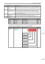
Function Code
Parameter Name
Setting Range
Default
A8-01
Master or slave selection
0: Master
1: Slave
0
This function parameter determines whether the AC drive is master or slave.
Summary of Contents for MD290 Series
Page 1: ......
Page 79: ...3 Electrical Installation 78 3 ...
Page 80: ...4 Operating Panel Keypad Display 4 1 Introduction 80 4 2 Inbuilt LED Operating Panel 80 ...
Page 92: ...5 Quick Setup 5 1 Get Familiar With Operating Panel 92 5 2 Setup Flowchart 93 ...
Page 227: ...7 Interfaces and Communication 226 7 ...
Page 285: ...10 Troubleshooting 284 11 ...
Page 349: ......
Page 350: ......


