6. Description of Parameters
- 172 -
6
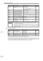
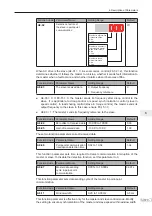
Figure 6-51 User programmable function (2)
Set the
drive
outputs.
FMR
(FM used as digital
output)
Relay1
(T/A-T/B-T/C)
DO1
FMP
(FM used as pulse
output)
AO1
Control mode
(units position
of A7-01)
Control mode
(tens position
of A7-01)
Control mode
(hundreds
position
of A7-01)
Control mode
(thousands
position
of A7-01)
0
1
AC drive control
(See details in
group F5)
PLC program
control
0
1
AC drive control
(See details in
group F5)
PLC program
control
0
1
AC drive control
(See details in
group F5)
PLC program
control
PLC controls
digital output.
(units position
of A7-05)
0
1
AC drive control
(See details in
group F5)
PLC program
control
PLC controls
FMP output.
(A7-03)
0.0% to 100.0%
Base value of percentage is
FMP output max. frequency
(F5-09).
0
1
AC drive control
(See details in
group F5)
PLC program
control
PLC controls
AO1 output
(A7-04)
0.0% to 100.0%
Base value of percentage
is 10 V or 20 mA.
PLC program modified
A7-00 = 1
Set the
programmable card
to activate.
0: output invalid
0: output invalid
0: output invalid
1: output valid
Control mode
(ten thousands
position
of A7-01)
1: output valid
1: output valid
PLC controls
digital output
(tens position of A7-05)
PLC controls
digital output
(units position
of A7-05)
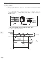
Figure 6-52 The user programmable use schematic (3)
Command
ǂ
0: No command
ǂ
1: Forward run
ǂ
2: Reverse run
ǂ
3: Forward jog
ǂ
4: Reverse jog
ǂ
5: Coast to stop
ǂ
6: Decelerate to stop
ǂ
7: Fault reset
PLC program modified
Frequency
reference
PLC program modified
Fault
PLC program modified
ǂ
0: No fault
ǂ
80 to 89: User-defined
A7-00 = 1
Set the
programmable card
to activate.
The frequency reference is set
via communication.
For details, see section 6.2.
The running command is
given by the communication.
Set F0-02 = 2.
The value of A7-08 is
determined by the user
programmable card.
The value of A7-06 is
determined by the user
programmable card.
fault code
The value of A7-09 is
determined by the user
programmable card.
-100.0% to 100.0%
The base value of the percentage
is F0-10 (Max. frequency).
Summary of Contents for MD290 Series
Page 1: ......
Page 79: ...3 Electrical Installation 78 3 ...
Page 80: ...4 Operating Panel Keypad Display 4 1 Introduction 80 4 2 Inbuilt LED Operating Panel 80 ...
Page 92: ...5 Quick Setup 5 1 Get Familiar With Operating Panel 92 5 2 Setup Flowchart 93 ...
Page 227: ...7 Interfaces and Communication 226 7 ...
Page 285: ...10 Troubleshooting 284 11 ...
Page 349: ......
Page 350: ......

