6. Description of Parameters
- 133 -
6
Function Code
Parameter Name
Setting Range
Default
F0-07
Final frequency
reference setting
selection
Main and auxiliary calculation
relationship
0: Main + auxiliary
1: Main
̢
auxiliary
2: Max. (main, auxiliary)
3: Min. (main, auxiliary)
Final frequency reference selection
0: Main frequency reference
1: Main and auxiliary calculation result
2: Switchover between main frequency
reference and auxiliary frequency
reference
3: Switchover between main frequency
reference and main and auxiliary
calculation result
4: Switchover between auxiliary
frequency reference and main and
auxiliary calculation result
00
F0-05
Base value of range
of auxiliary frequency
reference for main and
auxiliary superposition
0: Relative to maximum frequency
1: Relative to main frequency reference
0
F0-06
Range of auxiliary
frequency reference
for main and auxiliary
superposition
0% to 150%
100%
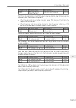
:KHQPDLQIUHTXHQF\UHIHUHQFHDQGDX[LOLDU\IUHTXHQF\UHIHUHQFHDUHXVHGIRUFDOFXODWLRQ¿QDO
frequency reference is set by "main and auxiliary calculation"), pay attention to the following
aspects:
Ɣ
If auxiliary frequency reference is digital setting, preset frequency (F0-08) does not take
effect. You can directly adjust auxiliary frequency reference by pressing keys
and
on the operating panel (or using the UP/DOWN function of input terminals) based on main
frequency reference.
Ɣ
If auxiliary frequency reference is set via analog input (AI1, AI2 and AI3) or pulse reference,
100% of the input corresponds to range of the auxiliary frequency reference (set in F0-05
and F0-06). This is valid for main and auxiliary calculation.
Ɣ
Main frequency reference and auxiliary frequency reference must not use the same setting
channel. That is, F0-03 and F0-04 cannot be set to the same value.
Ɣ
Main & auxiliary calculation can be used for closed-loop speed control. An example of this is
to use main frequency reference to set a required frequency reference and to use auxiliary
frequency reference for automatic adjustment. Closed-loop control is implemented when this
method is used with switchover performed by an external DI terminal signal.
Summary of Contents for MD290 Series
Page 1: ......
Page 79: ...3 Electrical Installation 78 3 ...
Page 80: ...4 Operating Panel Keypad Display 4 1 Introduction 80 4 2 Inbuilt LED Operating Panel 80 ...
Page 92: ...5 Quick Setup 5 1 Get Familiar With Operating Panel 92 5 2 Setup Flowchart 93 ...
Page 227: ...7 Interfaces and Communication 226 7 ...
Page 285: ...10 Troubleshooting 284 11 ...
Page 349: ......
Page 350: ......


