3. Electrical Installation
- 51 -
3
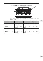
Figure 3-2 Terminal dimensions of MD290T30G/37P and MD290T37G/45P
16.5
20.2
18
20.2
20.2 20.2
161.6
M6 combination scre
w
R
S
T
U
V
W
POWER
MOTOR
BR (+) (-)
Table 3-3 Recommended cable dimensions and tightening torque of MD290T30GB/37P and
MD290T37GB/45P
AC Drive Model
Rated Input
Current (A)
Power Input/
Output Cable
Crimp
Terminal
Model
Ground
Cable
Crimp
Terminal
Model
Tightening
Torque
(N·m)
Screw
Spec.
MD290T30G
57
3 x 16 mm
2
3 x 4 AWG
14-L6
16 mm
2
8 AWG
8-6
4.0
M6
MD290T37P
71
3 x 16 mm
2
3 x 4 AWG
14-L6
16 mm
2
8 AWG
8-6
4.0
M6
MD290T37G
69
3 x 16 mm
2
3 x 4 AWG
14-L6
16 mm
2
8 AWG
8-6
4.0
M6
MD290T45P
86
3 x 25 mm
2
3 x 3 AWG
22-8
25 mm
2
6 AWG
14-8
4.0
M6
Summary of Contents for MD290 Series
Page 1: ......
Page 79: ...3 Electrical Installation 78 3 ...
Page 80: ...4 Operating Panel Keypad Display 4 1 Introduction 80 4 2 Inbuilt LED Operating Panel 80 ...
Page 92: ...5 Quick Setup 5 1 Get Familiar With Operating Panel 92 5 2 Setup Flowchart 93 ...
Page 227: ...7 Interfaces and Communication 226 7 ...
Page 285: ...10 Troubleshooting 284 11 ...
Page 349: ......
Page 350: ......


