6. Description of Parameters
- 206 -
6
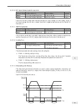
6.11.8 Current Detection
The drive provides two groups of current detection level and width.
If output current of the AC drive reaches the width, digital output terminals set for functions 28
and 29 become on.
Figure 6-64 Current detection
OFF
OFF
OFF
ON
ON
ON
Output current
Current detection level
Current detection signal
Current detection width
Current detection width
DO or relay
Function Code
Parameter Name
Setting Range
Default
F8-38
Detection level of current 1
0.0% to 300.0% (rated motor current)
100.0%
F8-39
Detection width of current 1
0.0% to 300.0% (rated motor current)
0.0%
F8-40
Detection level of current 2
0.0% to 300.0% (rated motor current)
100.0%
F8-41
Detection width of current 2
0.0% to 300.0% (rated motor current)
0.0%
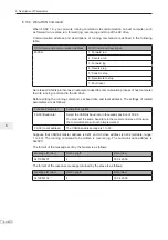
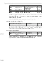
6.11.9 Timing Function
Function Code
Parameter Name
Setting Range
Default
F8-42
Timing function
0: Disabled
1: Enabled
0
F8-43
Running time setting channel
0: Set by F8-44
1: AI1
2: AI2
3: AI3
(100% of analog input corresponds
to the value of F8-44)
0
F8-44
Running time
0.0 to 6500.0 min
0.0
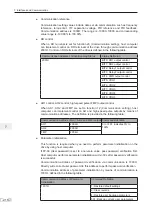
7KHVHIXQFWLRQSDUDPHWHUVGH¿QHWKHWLPLQJIXQFWLRQRIWKHGULYH2QFHLWLVHQDEOHGWKH$&
drive starts timing since start. When the set timing running time is reached, the AC drive stops
automatically and digital output terminal set for function 30 becomes on.
The AC drive starts timing from 0 again for each start. You can view remaining timing running
time in U0-20.
Summary of Contents for MD290 Series
Page 1: ......
Page 79: ...3 Electrical Installation 78 3 ...
Page 80: ...4 Operating Panel Keypad Display 4 1 Introduction 80 4 2 Inbuilt LED Operating Panel 80 ...
Page 92: ...5 Quick Setup 5 1 Get Familiar With Operating Panel 92 5 2 Setup Flowchart 93 ...
Page 227: ...7 Interfaces and Communication 226 7 ...
Page 285: ...10 Troubleshooting 284 11 ...
Page 349: ......
Page 350: ......


