6. Description of Parameters
- 173 -
6
Ƶ
Parameter Settings of Controlling MD290 by PLC Programming Function
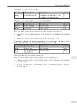
1. Set whether user programmable card is valid.
Function Code
Parameter Name
Setting Range
Default
A7-00
User programmable function
selection
0: Disabled
1: Enabled
0
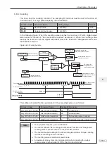
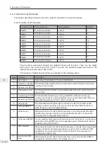
2. Set AI3 and AO2 function on user programmable card.
Function Code
Parameter Name
Setting Range
Default
A7-02
User programmable card AI3
and AO2 function selection
0 to 7
0: AI3 (voltage input), AO2
(voltage output)
1: AI3 (voltage input), AO2
(current output)
2: AI3 (current input), AO2
(voltage output)
3: AI3 (current input), AO2
(current output)
4: AI3 (PTC input), AO2
(voltage output)
5: AI3 (PTC input), AO2
(current output)
6: AI3 (PT100 input), AO2
(voltage output)
7: AI3 (PT100 input), AO2
(current output)
0
The user programmable card provides an analog input terminal AI3 and an analog
output terminal AO2. Set DIP switch S1, jumper J2 and jumper J3 on the card and
then set A7-02. Setting of S1, S2 and J3 must be consistent with setting in A7-02.
Otherwise, communication will be abnormal.
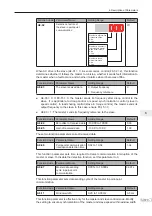
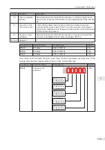
3. Set the AC drive output signals
When A7-00 = 1 (user programmable card is enabled), you can set control source of
output terminals (FMR, relay, DO1, FMP and AO1) of the AC drive in A7-01.
When an output terminal is controlled by PLC program, output of terminal is
determined by setting of corresponding function parameter A7-03/A7-04/A7-05.
You can implement control of output terminal via PLC program by modifying A7-03/
A7-04/A7-05.
Summary of Contents for MD290 Series
Page 1: ......
Page 79: ...3 Electrical Installation 78 3 ...
Page 80: ...4 Operating Panel Keypad Display 4 1 Introduction 80 4 2 Inbuilt LED Operating Panel 80 ...
Page 92: ...5 Quick Setup 5 1 Get Familiar With Operating Panel 92 5 2 Setup Flowchart 93 ...
Page 227: ...7 Interfaces and Communication 226 7 ...
Page 285: ...10 Troubleshooting 284 11 ...
Page 349: ......
Page 350: ......


