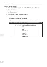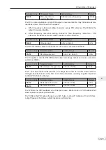
6. Description of Parameters
- 119 -
6
Ƶ
Multi-reference
Multi-reference is a relative value and is a percentage of F0-10 (max. frequency).
Whether the setting is positive or negative determines drive running direction. If negative,
it indicates that the AC drive runs in reverse direction.
Multiple frequency references are set in group FC, as listed in the following table.
Function Code
Parameter Name
Setting Range
Default
FC-00
Reference 0
-100.0% to 100.0%
0.0%
FC-01
Reference 1
-100.0% to 100.0%
0.0%
FC-02
Reference 2
-100.0% to 100.0%
0.0%
FC-03
Reference 3
-100.0% to 100.0%
0.0%
FC-04
Reference 4
-100.0% to 100.0%
0.0%
FC-05
Reference 5
-100.0% to 100.0%
0.0%
FC-06
Reference 6
-100.0% to 100.0%
0.0%
FC-07
Reference 7
-100.0% to 100.0%
0.0%
FC-08
Reference 8
-100.0% to 100.0%
0.0%
FC-09
Reference 9
-100.0% to 100.0%
0.0%
FC-10
Reference 10
-100.0% to 100.0%
0.0%
FC-11
Reference 11
-100.0% to 100.0%
0.0%
FC-12
Reference 12
-100.0% to 100.0%
0.0%
FC-13
Reference 13
-100.0% to 100.0%
0.0%
FC-14
Reference 14
-100.0% to 100.0%
0.0%
FC-15
Reference 15
-100.0% to 100.0%
0.0%
In multi-reference mode, combinations of different DI terminal states correspond to
different frequency references. The AC drive supports a maximum of 16 references
implemented by 16 state combinations of four DI terminals (allocated with functions 12 to
15) in Group FC.
If a DI terminal is used for the multi-reference function, you need to set related parameters
in group F4.
The below diagram Figure 6-20 shows an example of 4 multi-frequency settings.
Figure 6-20 Using multi-reference to control frequency reference
DI4
DI2
DI8
DI7
FC-00
0
0
0
1
1
0
0
0
1
1
0
0
1
1
1
0
1
0
0
1
.
.
F4-01
Function
Code
12
Setting
F4-03
13
F4-06
14
F4-07
15
Set the four terminals for the
multi-reference function.
FC-01
FC-02
...
FC-14
FC-15
State combination
(Binary)
Max. frequency
F0-03 = 6
Select multi-reference as main
frequency reference setting channel.
F0-07 = 0
F0-27 = 0
x (F0-10)
16 frequency
references (%)
Final
frequency
reference
Summary of Contents for MD290 Series
Page 1: ......
Page 79: ...3 Electrical Installation 78 3 ...
Page 80: ...4 Operating Panel Keypad Display 4 1 Introduction 80 4 2 Inbuilt LED Operating Panel 80 ...
Page 92: ...5 Quick Setup 5 1 Get Familiar With Operating Panel 92 5 2 Setup Flowchart 93 ...
Page 227: ...7 Interfaces and Communication 226 7 ...
Page 285: ...10 Troubleshooting 284 11 ...
Page 349: ......
Page 350: ......


