Appendix
- 317 -
12
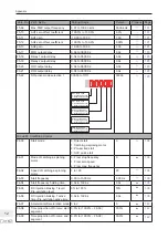
Para. No. Para. Name
Setting Range
Default
Property
Page
F6-10
Stop mode
0: Decelerate to stop
1: Coast to stop
0
ƿ
139
F6-11
DC injection braking 2 start
frequency
0.00 Hz to maximum frequency
0.00 Hz
ƿ
139
F6-12
DC injection braking 2 delay
time
0.0 to 100.0s
0.0s
ƿ
139
F6-13
DC injection braking 2 level
0% to 100%
50%
ƿ
139
F6-14
DC injection braking 2 active
time
0.0s to 100.0s
0.0s
ƿ
139
F6-15
Braking use ratio
0% to 100%
100%
ƿ
-
F6-18
Catching a spinning motor
current limit
30% to 200%
Model
dependent
ƾ
-
F6-21
Demagnetization time
0.00s to 5.00s
Model
dependent
ƿ
-
Group F7: Keypad Operation and LED Display
F7-00
LED default display check
0: Disabled
1: Enabled
0
ƿ
-
F7-01
MF.K key function selection
0: MF.K key disabled
1: Switchover from remote control
(terminal or communication) to
keypad control
2: Switchover between forward
rotation and reverse rotation
3: Forward jog
4: Reverse jog
0
ƾ
-
F7-02
STOP/RESET key function
0: STOP/RESET key enabled only
in keypad control
1: STOP/RESET key enabled in
any operation mode
1
ƿ
-
F7-03
LED display running parameters 1
0000 to FFFF
7
6
5
4
3
2
1
0
Running frequency 1 (Hz)
Frequency reference (Hz)
Bus voltage (V)
Output voltage (V)
Output current (A)
Output power (kW)
Output torque (%)
DI state (V)
15
14
12
11
10 9
8
DO state
AI1 voltage (V)
Count value
Length value
Load speed display
PID reference
13
AI2 voltage (V)
AI3 voltage (V)
1F
ƿ
161
Summary of Contents for MD290 Series
Page 1: ......
Page 79: ...3 Electrical Installation 78 3 ...
Page 80: ...4 Operating Panel Keypad Display 4 1 Introduction 80 4 2 Inbuilt LED Operating Panel 80 ...
Page 92: ...5 Quick Setup 5 1 Get Familiar With Operating Panel 92 5 2 Setup Flowchart 93 ...
Page 227: ...7 Interfaces and Communication 226 7 ...
Page 285: ...10 Troubleshooting 284 11 ...
Page 349: ......
Page 350: ......


