6. Description of Parameters
- 154 -
6
For example, application requires detect of Err11 when motor runs at 150% of rated motor
current for two minutes.
According to Figure 7-47, 150% (I) is in the range of 145% (I1) and 155% (I2). 145% corresponds
to overload protection time 6 minutes (T1) and 145% corresponds to overload protection time
4 minutes (T2). You can calculate overload protection time T corresponding to 150% from the
following formula:
T = T1 + (T2 - T1) x (I - I1) / (I2-I1) = 4 + (6 - 4) x (150% - 145%) / (155%-145%) = 5 minutes
Then calculate motor overload protection gain from the following formula: F9-01 = Desired
overload protection time / Corresponding overload protection time = 2 / 5 = 0.4.
Note
7KHPRWRUVKRXOGEH¿WWHGZLWKRYHUWHPSHUDWXUHVHQVRUVHJ37&DQGZLUHGWRD
protection relay. Such protection devices measure actual motor winding temperature
and is the ultimate protection.
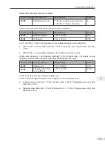
Function Code
Parameter Name
Setting Range
Default
F9-02
Motor overload pre-warning
FRHI¿FLHQW
50% to 100%
80%
The AC drive has the motor overload pending function that reminds of motor overload in advance
through digital output function 6.
On the condition that F9-01 = 1.00 and F9-02 = 80%, when motor running current reaches 145%
of rated motor current and motor runs at this level for 80% x 6 = 4.8 minutes, DO terminal or fault
relay outputs the motor overload pending signal.
When F9-02 = 100%, the motor overload pending and the motor overload protection are
performed simultaneously.
6.6.2 Phase Loss Protection
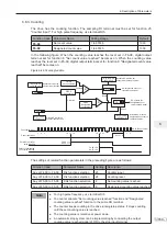
Function Code
Parameter Name
Setting Range
Default
F9-12
Input phase loss/pre-
charge relay protection
Pre-charge relay protection
0: Disabled
1: Enabled
Input phase loss
0: Disabled
1: Enabled
11
This function parameter determines whether to perform input phase loss or pre-charge relay
protection. The input phase loss detection function is disabled when the AC drive is in stop status
or when output power is below 20% of rated AC drive power.
Summary of Contents for MD290 Series
Page 1: ......
Page 79: ...3 Electrical Installation 78 3 ...
Page 80: ...4 Operating Panel Keypad Display 4 1 Introduction 80 4 2 Inbuilt LED Operating Panel 80 ...
Page 92: ...5 Quick Setup 5 1 Get Familiar With Operating Panel 92 5 2 Setup Flowchart 93 ...
Page 227: ...7 Interfaces and Communication 226 7 ...
Page 285: ...10 Troubleshooting 284 11 ...
Page 349: ......
Page 350: ......

