6. Description of Parameters
- 151 -
6
6.5.4 Voltage Limit and Braking Unit Applied Voltage
When bus voltage rises above the value set in F3-22, the motor becomes regenerative. This
function prevents overvoltage trips by adjusting the output frequency to extend deceleration time
in this case.
If actual deceleration time cannot satisfy the requirement, increase the value of F3-10 (V/F over-
excitation gain) adequately.
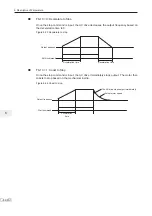
Figure 6-42 Voltage limit
Time
Time
Output
frequency
Time
Time
Voltage limit
Voltage limit
Time
Time
Voltage limit
during acceleration
Voltage limit
during constant running
Voltage limit
during deceleration
Bus
voltage
Bus
voltage
Bus
voltage
Output
frequency
Output
frequency
Voltage limit
Voltage limit
Voltage limit
Voltage limit
Function Code
Parameter Name
Setting Range
Default
F3-22
Voltage limit
650 to 800 V
760 V
F3-23
Voltage limit selection
0: Disabled
1: Enabled
1
F3-24
Frequency gain for voltage limit
0 to 100
30
F3-25
Voltage gain for voltage limit
0 to 100
30
F3-26
Frequency rise threshold during
voltage limit
0 to 50 Hz
5 Hz
F9-08
Braking unit applied voltage
650 to 800 V
760 V
F3-10
V/F over-excitation gain
0 to 200
64
F3-11
V/F oscillation suppression
gain
0 to 100
40
Note
When using braking resistor, braking unit or energy feedback unit, pay attention to
the following aspects:
Ɣ
Set F3-10 (V/F over-excitation gain) to 0. Otherwise, too large current may occur
during drive running.
Ɣ
Set F3-23 (overvoltage suppression selection) to 0 (disabled). Otherwise, the
deceleration time may become longer.
Summary of Contents for MD290 Series
Page 1: ......
Page 79: ...3 Electrical Installation 78 3 ...
Page 80: ...4 Operating Panel Keypad Display 4 1 Introduction 80 4 2 Inbuilt LED Operating Panel 80 ...
Page 92: ...5 Quick Setup 5 1 Get Familiar With Operating Panel 92 5 2 Setup Flowchart 93 ...
Page 227: ...7 Interfaces and Communication 226 7 ...
Page 285: ...10 Troubleshooting 284 11 ...
Page 349: ......
Page 350: ......


