

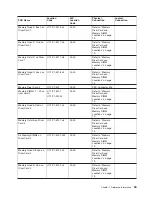
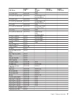
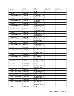
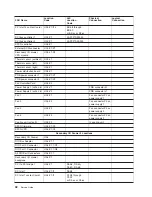
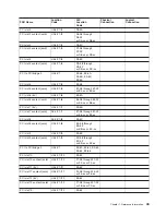
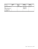


FRU
Name
Location
Code
AIX
Location
Code
Physical
Connection
Logical
Connection
PCI
slot
11
(5V)
U0.1-P1/I11
20-62
PCI
slot
11
content
(card)
U0.1-P1-I11
34-08
through
34-0F
or
35-xx
or
36-xx
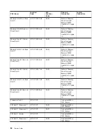
PCI
slot
12
(5V)
U0.1-P1/I12
20-63
PCI
slot
12
content
(card)
U0.1-P1-I12
37-08
through
37-0F
or
38-xx
or
39-xx
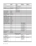
PCI
slot
13
U0.1-P1/I13
20-64
PCI
slot
13
content
(card)
U0.1-P1-I13
3A-08
through
3A-0F
or
3B-xx
or
3C-xx
PCI
slot
14
U0.1-P1/I14
20-66
PCI
slot
14
content
(card)
U0.1-P1/I14
3D-08
through
3D-0F
or
3E-xx
or
3F-xx
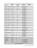
PCI
bus
controller
0
U0.1-P1
00-FFF7F08000
PCI
bus
controller
1
U0.1-P1
00-FFF7F09000
PCI
bus
controller
2
U0.1-P1
00-FFF7F0A000
ISA
Bus
U0.1-P1
10-80
Service
Processor
U0.1-P1
JTAG
Connector
U0.1-P1/Q4
NVRAM
U0.1-P1
Service
Processor
ISA
Bridge
U0.1-P1
Real
Time
Clock
(RTC)
U0.1-P1
Timer
U0.1-P1
Interrupt
Controller
U0.1-P1
DMA
Controller
U0.1-P1
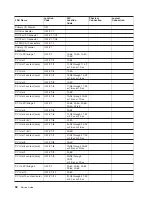
Diskette
controller
U0.1-P1-D1
01-D1
Diskette
drive
U0.1-P1/D1
01-D1-00-00
Keyboard
controller
/
connector
U0.1-P1/K1
01-K1-00
Keyboard
U0.1-P1/K1
01-K1-00-00
Mouse
controller
U0.1-P1/K1
01-K1-01
Mouse
connector
U0.1-P1-01
01-K1-01
Mouse
U0.1-P1-01
01-K1-01-00
Parallel
port
connector
U0.1-P1/R1
01-R1
Serial
port
1
connector
U0.1-P1/S1
01-S1
Serial
port
2
connector
U0.1-P1/S2
01-S2
Serial
port
3
connector
U0.1-P1/S3
01-S3
Serial
port
4
connector
U0.1-P1/S4
01-S4
Thermal
sensor
(ambient)
U0.1-L1
Thermal
sensor
(left)
U0.1-P1
Chapter
1.
Reference
Information
37
Summary of Contents for RS/6000 Enterprise Server M80
Page 1: ...RS 6000 Enterprise Server Model M80 Eserver pSeries 660 Model 6M1 Service Guide SA38 0571 01...
Page 10: ...x Service Guide...
Page 14: ...xiv Service Guide...
Page 16: ...xvi Service Guide...
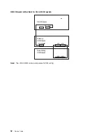
Page 22: ...Data Flow 4 Service Guide...
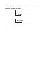
Page 30: ...CEC Card Cage Rear of CEC drawer viewed from top cover removed 12 Service Guide...
Page 84: ...66 Service Guide...
Page 176: ...158 Service Guide...
Page 376: ...358 Service Guide...
Page 430: ...412 Service Guide...
Page 485: ...Chapter 11 Parts Information This chapter contains parts information for the system 467...
Page 486: ...CEC Drawer Card Assembly 9 468 Service Guide...
Page 488: ...CEC Drawer Backplane 5 2a 1 2 3 4 470 Service Guide...
Page 490: ...CEC Drawer Power Supplies 1 2 3 4 5 6 7 8 9 472 Service Guide...
Page 492: ...CEC Drawer Fan Assemblies 2 1 3 4 5 6 8 9 10 11 12 13 7 14 474 Service Guide...
Page 496: ...7 8 9 10 6 1 2 3 4 4 5 478 Service Guide...
Page 508: ...490 Service Guide...
Page 520: ...502 Service Guide...
Page 522: ...504 Service Guide...
Page 526: ...508 Service Guide...
Page 558: ...540 Service Guide...
Page 565: ......